volkswagen Workshop Repair Guides

Volkswagen Workshop Service and Repair Manuals

Checking air conditioning system signal to engine speed adaption > < Checking signal from/to air conditioning system
Checking compressor shut-off
The engine control unit receives the information that the air conditioner will be switched on shortly via the air conditioner ready signal.
Through another wiring connection, the engine control has the possibility of switching off the air conditioner compressor for various operating conditions:
t  Hard acceleration from low speed
t  Emergency programme (emergency running operation)
t  Coolant temperatures above + 120 °C
t  After each starting process for approx. 6 seconds.
Test procedure
–  Connect fault reader -V.A.G 1551- or vehicle system tester -V.A.G 1552- and select engine electronics control unit with “address word 01”. Engine must be idling. (Connect fault reader and select engine electronics control unit → Chapter.)
   
Indicated on display:
–  Press buttons 0 and 3 for function “Final control diagnosis”.
 
Rapid data transfer                 HELP
Select function XX                    
Indicated on display:
–  Confirm entry with Q button.
 
Rapid data transfer                    Q
03-Final control diagnosis                   
Indicated on display:
–  Press button.
 
Final control diagnosis               ->
Commencement of injection valve N108          
Indicated on display:
–  Press button.
 
Final control diagnosis               ->
Exhaust gas recirculation valve N18          
Indicated on display:
Air conditioner compressor switch-off is checked.
The air conditioner compressor must stop within 5 seconds (visual check) then start approx. every 5 seconds and then stop again.
If the conditioner compressor is not switched off:
–  Proceed with final control diagnosis until completed.
–  Press buttons 0 and 6 for function “End data transfer” and confirm entry with Q button.
 
Final control diagnosis               ->
Conditioner compressor interruption                 
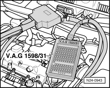
–  Connect adapter cable, 121-pin -V.A.G 1598/31- to control unit wiring harness.
–  Check line between adapter cable, 121-pin -V.A.G 1598/31- socket 29 and air conditioning for open circuit according to current flow diagram → Current flow diagrams, Electrical fault finding and Fitting locations.
Cable resistance: max. 1.5 Ω.
  N24-0943

Checking air conditioning system signal to engine speed adaption > < Checking signal from/to air conditioning system