volkswagen Workshop Repair Guides

Volkswagen Workshop Service and Repair Manuals

Checking intake manifold flap change-over > < Checking injection timing control range
Checking air mass meterG70
Checking air mass meter -G70-
Engine codes AGR, AHF, ALH, ASV
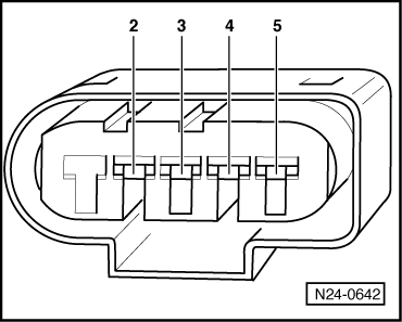
The air mass meter signal is used by the control unit to calculate the quantity injected and to control the required exhaust gas recirculation. The smaller the signal from air mass meter -G70- the smaller the quantity of fuel injected.
Special tools and workshop equipment required
t  Fault reader -V.A.G 1551- or vehicle system tester -V.A.G 1552- with diagnosis cable -V.A.G 1551/3-
t  
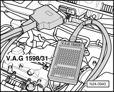
Adapter cable, 121-pin -V.A.G 1598/31-
t  Hand multimeter -V.A.G 1526C- or multimeter -V.A.G 1715-
t  Auxiliary measuring set -V.A.G 1594C-
t  Current flow diagram
Test procedure
–  Connect fault reader -V.A.G 1551- or vehicle system tester -V.A.G 1552- and select engine electronics control unit with “address word 01”. Engine must be idling. (Connecting fault reader and selecting engine electronics control unit → Chapter.)
  WARNING
Secure fault reader to rear seat and operate from this position.
   
Indicated on display:
–  Press buttons 0 and 8 for function “Read measured value block” and confirm entry with Q button.
 
Rapid data transfer                 HELP
Select function XX                    
Indicated on display:
–  Press buttons 0, 1 and 0 for “Display group number 10” and confirm entry with Q button.
–  Observe display in display zone 1.
 
Read measured value block           HELP
Input display group number XXX       
–  Specification: 230...370 mg/stroke
If the specification is not achieved:
–  Checking exhaust gas recirculation → 4-cyl. diesel engine, mechanical system; Rep. Gr.26.
If the specification is attained:
–  Accelerate vehicle from approx. 1500 rpm at full throttle; in second gear for manual gearbox or second driving range for automatic gearbox.
–  At approx. 3000 rpm, press PRINT button on fault reader -V.A.G 1551-.
Accelerator must be fully depressed at this moment.
 
Read measured value block 10          ->
309 mg/H  1027 mbar   1011 mbar    0.0%
–  Specification in display zone 4: 100 % (accelerator pedal position)
If the specification is not achieved:
–  Repeat test and accelerate vehicle at full throttle.
 
Read measured value block 10          ->
830 mg/H  1027 mbar   1850 mbar    100%
–  Specification in display zone 1: above 800 mg/stroke (intaken air mass).
If the specification is not achieved:
–  Renew air mass meter -G70-.
If a constant 550 mg/H (predetermined replacement value) is displayed in display zone 1.
–  Press button.
–  Press buttons 0 and 6 for function “End data transfer” and confirm entry with Q button.
–  Switch off ignition.
–  Separate connector for air mass meter -G70- → Chapter.
–  Switch on ignition.
 
Read measured value block 10          ->
830 mg/H  1027 mbar   1850 mbar    100%
–  Measure voltage supply for air mass meter -G70- between following connector contacts:
  N24-0642
Connector on air mass meter -G70-
contact
Specification
2 + earthApp. battery voltage
2 + 3App. battery voltage
4 + earthApprox. 5 V
4 + 3Approx. 5 V

If the specifications are not achieved:
–  Switch off ignition.
   
–  Connect adapter cable, 121-pin -V.A.G 1598/31- to control unit wiring harness.
  N24-0943
–  Check wiring between 121-pin adapter cable -V.A.G 1598/31- and connector for open circuit referring to current flow diagram.
Contact 2+ sockets 1 and 2 Contact 3+ socket 49 Contact 4+ socket 30 Contact 5+ socket 68 Line resistance: max. 1.5 Ω
–  Also check wiring for short to one another, short to vehicle earth and short to battery positive.
Specification: ∞ Ω.
If no fault in lines is detected:
–  Renew diesel direct injection system control unit -J248- → Chapter.
  N24-0642

Checking intake manifold flap change-over > < Checking injection timing control range