volkswagen Workshop Repair Guides

Volkswagen Workshop Service and Repair Manuals

Checking coolant temperature sender G62 > < Checking engine speed sender G28
Checking intake manifold pressure senderG71 and altitude senderF96
Checking intake manifold pressure sender -G71- and altitude sender -F96-
Engine codes AGR, AHF, ALH, ASV
Special tools and workshop equipment required
t  Fault reader -V.A.G 1551- or vehicle system tester -V.A.G 1552- with diagnosis cable -V.A.G 1551/3-
t  Adapter cable, 121-pin -V.A.G 1598/31-
t  Hand multimeter -V.A.G 1526C- or multimeter -V.A.G 1715-
   
t  Turbocharger tester -V.A.G 1397A-
t  Auxiliary measuring set -V.A.G 1594C-
t  Current flow diagram
Altitude sender -F96- is located in diesel direct injection system control unit -J248-. The intake manifold pressure sender -G71- is a separate component and is located together with intake manifold temperature sender -G72- in a common housing on the charge air cooler.
Test procedure
–  Connect fault reader -V.A.G 1551- or vehicle system tester -V.A.G 1552- and select engine electronics control unit with “address word 01”. The ignition must be switched on for this purpose. (Connecting fault reader and selecting engine electronics control unit → Chapter.)
  W00-0565
Indicated on display:
–  Press buttons 0 and 8 for function “Read measured value block” and confirm entry with Q button.
 
Rapid data transfer                 HELP
Select function XX                    
Indicated on display:
–  Press buttons 0, 1 and 0 for “Display group number 10” and confirm entry with Q button.
 
Read measured value block          HELP
Input display group number XXX      
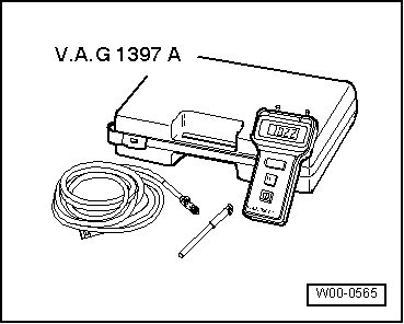
–  Compare display in display zone 2 (altitude sender -F96-), display zone 3 (intake manifold pressure sender -G71-) and display on turbocharger tester -V.A.G 1397A- with one another. Specification:
Pressures must correspond (tolerance ± 30 mbar)
  Note
The turbocharger tester -V.A.G 1397A- is required to provide an independent figure for comparison. The turbocharger tester -V.A.G 1397A- must be set to measuring range I (absolute pressure). A barometer can be used instead.
Value in display zone 2 deviates:
–  Press button.
–  Press buttons 0 and 6 for function “End data transfer” and confirm entry with Q button.
–  Switch off ignition.
–  Renew diesel direct injection system control unit -J248- → Chapter.
Value in display zone 3 deviates:
–  Remove right headlight → Electrical system; Rep. Gr.94
–  Press button.
–  Press buttons 0 and 6 for function “End data transfer” and confirm entry with Q button.
–  Start engine and select function 08 “Read measured value block” again.
–  Press buttons 0, 1 and 0 for “Display group number 10” and confirm entry with Q button.
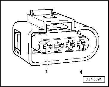
–  Disconnect connector for intake manifold pressure sender -G71- → Chapter.
–  Observe value in display zone 3 (intake manifold pressure sender -G71-).
 
Read measured value block 10          ->
  0 mg/H   1027 mbar   1013 mbar   0.0%
–  It must drop briefly to approx. 400 mbar and then assume the value of the altitude sender -F96- (display zone 2).
If the specification is attained:
–  Renew intake manifold pressure sender -G71- with intake manifold temperature sender -G72-.
If the specification is not achieved:
–  Press button.
–  Press buttons 0 and 6 for function “End data transfer” and confirm entry with Q button.
–  Switch off ignition.
 
Read measured value block 10         ->
  515 mg/H  1009mbar   1009 mbar  0.0% 
–  Connect adapter cable, 121-pin -V.A.G 1598/31- to control unit wiring harness.
  N24-0943
–  Check wiring between adapter cable, 121-pin -V.A.G 1598/31- and connector for open circuit referring to current flow diagram.
Contact 3+socket 31 Contact 4+socket 71 Line resistance: Max. 1.5 Ω
–  Also check wiring for short to one another, short to vehicle earth and short to battery positive.
Specification: ∞ Ω.
If no fault in lines is detected:
–  Renew diesel direct injection system control unit -J248- → Chapter.
  A24-0094

Checking coolant temperature sender G62 > < Checking engine speed sender G28