volkswagen Workshop Repair Guides

Volkswagen Workshop Service and Repair Manuals

Checking knock sensor > < Checking Hall sender
Motronic injection and ignition system (2.0 ltr. engine)
Servicing ignition system
Checking ignition coils with output stage

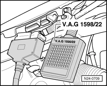
Special tools, workshop equipment, testers, measuring instruments and auxiliary items required

  • ◆ Test box V.A.G 1598/22
  • ◆ Hand multimeter V.A.G 1526 or multimeter V.A.G 1715
  • ◆ Adapter set V.A.G 1594
  • ◆ Diode test lamp V.A.G 1527
  • ◆ Current flow diagram

Check conditions

  • ● The battery voltage must be at least 11.5 V.
  • ● Hall sender must be OK, checking
    .
  • ● Engine speed sender must be OK, checking Page 24-62 .
 
N24-0588
  • ● → Fuse 29 must be OK.

Note:

  • ◆ Ignition coils and final output stages are one component and cannot be renewed individually.

Checking voltage supply

 
N28-0147
  • ‒ → Pull 4 pin connector -1- off output stage for ignition coils -2-.
  • ‒ Using multimeter and adapter cables from V.A.G 1594 measure the supply voltage between contacts 2+4 of disconnected connector.
  • ‒ Switch on ignition.
         Specification: Min. 11.5 V
  • ‒ Switch off ignition.

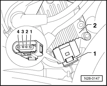
If no voltage is present:

 
N28-0147
  • ‒ → Check wire between 4 pin connector contact 2 and relay plate for open circuit according to current flow diagram.
         Wire resistance: max. 1.5 ω
  • ‒ Check wire between 4 pin connector contact 4 and earth for open circuit according to current flow diagram.
         Wire resistance: max. 1.5 ω

Checking activation

 
N24-0588
  • ‒ → Remove fuse 32

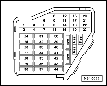
Note:

Removing fuse 32 interrupts the voltage supply to the injectors.

 
N28-0147
  • ‒ → Connect diode test lamp V.A.G 1527 with adapter cables from V.A.G 1594 to
         contacts 1 + 4 (ignition output 1),
         contacts 3 + 4 (ignition output 2)
    of disconnected connector.
  • ‒ Operate starter and check the ignition signal from engine control unit.
         The LED must flicker
  • ‒ Switch off ignition.

If the LED flickers and there is voltage between contacts 2 + 4:

  • ‒ Replace ignition coils (N, N128) , item 10 .

The LED does not flicker:

  • ‒ Check wiring => Page 28-13
 
N24-0709

Checking wiring

  • ‒ → Connect test box V.A.G 1598/22 to control unit wiring harness.
 
N28-0147
  • ‒ → Check wiring between test box and 4 pin connector for open circuit according to current flow diagram.
         Contact 1+socket 71
         Contact 3+socket 78
         Wire resistance: Max. 1.5 ω
  • ‒ Additionally check wires for short to one another.
         Contact 3+socket 71
         Specification: ∞ω

If no wiring fault is detected and voltage was present between contacts 2+4:

  • ‒ Renew engine electronics control unit => Page 24-114 .
 
N28-0115

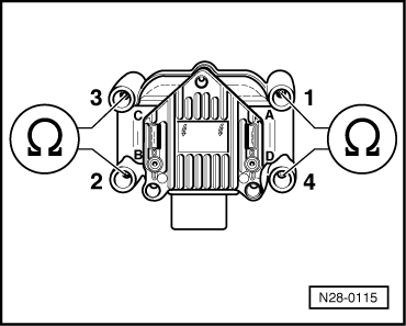
Checking secondary winding

  • ‒ → Check the secondary winding on terminal 4 between
         Cyl. 1+Cyl. 4,
         Cyl. 2+Cyl. 3.
         Specification: 4.0... 6.0 kω (at 20 °C)

If the specifications are not attained:

  • ‒ Replace ignition coils (N, N128) => Page 28-4 , item 10 .

Checking knock sensor > < Checking Hall sender