volkswagen Workshop Repair Guides

Volkswagen Workshop Service and Repair Manuals

Checking engine speed sender > < Checking coolant temperature sender
Motronic injection and ignition system (2.0 ltr. engine)
Checking components
Checking intake air temperature sender

Special tools, workshop equipment, testers, measuring instruments and auxiliary items required

  • ◆ Fault reader V.A.G 1551 or vehicle system tester V.A.G 1552 with cable V.A.G 1551/3
  • ◆ Test box V.A.G 1598/22
  • ◆ Hand multimeter V.A.G 1526 or multimeter V.A.G 1715
  • ◆ Adapter set V.A.G 1594
  • ◆ Current flow diagram
  • ◆ Chilling spray (commercially available)

Note:

If sender or connecting wiring is defective the control unit operates with a substitute temperature of 19.5 °C.

The intake air temperature sender (G42) is a part of the air mass meter (G70) and cannot be renewed individually.

Test sequence

  • ‒ Connect the fault reader V.A.G 1551 (V.A.G 1552). Then switch ignition on and select engine control unit with the "Address word" 01.
    (Connecting fault reader and selecting engine control unit .)
 
→ Indicated on display:
Rapid data transfer     HELP
Select function XX
  • ‒ Press keys 0 and 8 for the function "Read measured value block" and confirm entry with Q key.
 
→ Indicated on display:
Read measured value block     HELP
Input display group number XXX
  • ‒ Press keys 0, 0 and 4 for "Display group number 4" and confirm entry with Q key.
 
→ Indicated on display:
(1...4 = Display zones)
Read measured value block 4     ⇒
     1     2     3     4
  • ‒ Read off intake air temperature value in display zone 4.
         Specification: approx. ambient temperature

If the specification is not obtained:

  • ‒ Perform check according to following table:

Display

Cause

Continuation of check

approx. -46 °C

Open circuit or short to positive

=> Page 24-57

approx. 141 °C

Short to earth

=> Page 24-58

     1)     If a temperature is displayed which is below the ambient air temperature of the sender, check sender wiring for transfer resistances. Note when doing this that sender is heated from external sources, e.g. radiated heat when engine is not running.

If the specification is obtained:

  • ‒ Remove intake hose between air mass meter and throttle valve control part.
  • ‒ Note intake air temperature value in display zone 4.
 
N24-0765
  • ‒ → Spray sender -arrow- with commercial chilling agent whilst observing the temperature value. The temperature value must
         decrease.
  • ‒ Press ⇒key.
  • ‒ Press keys 0 and 6 for the function "End output" and confirm entry with the Q key.

Continuation of check when display reads approx. -46 °C:

 
N24-0789
  • ‒ → Pull 5 pin connector -1- off air mass meter -2-.
  • ‒ Bridge connector contacts 1 + 3 using aux. cables from V.A.G 1594 and observe display.

If display jumps to approx. 141 °C:

  • ‒ Press ⇒key.
  • ‒ Press keys 0 and 6 for the function "End output" and confirm entry with the Q key.
  • ‒ Switch off ignition.
  • ‒ Renew air mass meter (G70) , item 1 .

If display remains at approx. -46 °C:

  • ‒ Press ⇒key.
  • ‒ Press keys 0 and 6 for the function "End output" and confirm entry with the Q key.
  • ‒ Switch off ignition.
  • ‒ Check wiring using Current flow diagram
    => Page 24-60

Continuation of check when display reads approx. 141 °C:

 
N24-0789
  • ‒ → Pull 5 pin connector -1- off air mass meter -2-.

If display jumps to approx. -46 °C:

  • ‒ Press ⇒key.
  • ‒ Press keys 0 and 6 for the function "End output" and confirm entry with the Q key.
  • ‒ Switch off ignition.
  • ‒ Renew air mass meter (G70) , item 1 .

If display remains at approx. 141 °C:

  • ‒ Press ⇒key.
  • ‒ Press keys 0 and 6 for the function "End output" and confirm entry with the Q key.
  • ‒ Switch off ignition.
  • ‒ Check wiring using Current flow diagram
    => Page 24-60

Checking wiring

 
N24-0709
  • ‒ → Connect test box V.A.G 1598/22 to control unit wiring harness.
 
N24-0789
  • ‒ → Pull 5 pin connector -1- off air mass meter -2-.
  • ‒ Check wiring between test box and 5-pin connector -1- for open circuit using current flow diagram.
         Contact 1+socket 40
         Contact 3+socket 12
         Wire resistance: max. 1.5 ω
  • ‒ Check wiring additionally for short circuit to battery positive.
         Specification: ∞ω

If no fault in wire is detected:

 
N24-0789
  • ‒ → Perform a resistance measurement on intake air temperature sender (G42) contacts 1 (signal) and 3 (earth)
 
N24-0640

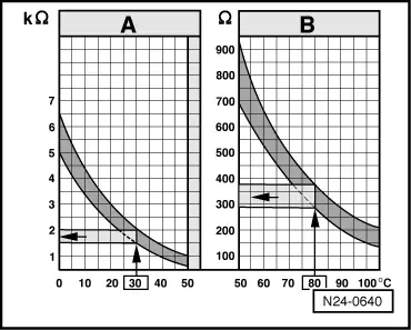
→ Scale A shows resistance values for temperature range 0...50 °C and scale B the values for temperature range 50...100 °C.

Examples:

  • ◆ 30 °C is in range A and corresponds to a resistance of 1.5...2.0 kω
  • ◆ 80 °C is in range B and corresponds to a resistance of 275...375 ω

If the specification is not obtained:

  • ‒ Renew air mass meter (G70) , item 1 .

If there is no fault in the wiring and the resistance measurement values are OK.:

  • ‒ Renew engine electronics control unit => Page 24-114 .

Checking engine speed sender > < Checking coolant temperature sender