volkswagen Workshop Repair Guides

Volkswagen Workshop Service and Repair Manuals

Checking engine speed sender > < Checking coolant temperature sender
Motronic injection and ignition system (5-cyl. engine)
Checking components
Checking intake manifold temperature sender

Special tools, testers, measuring instruments and auxiliary items required

  • ◆ Fault reader V.A.G 1551 or vehicle system tester V.A.G 1552 with cable V.A.G 1551/3
  • ◆ Test box V.A.G 1598/22
  • ◆ Hand multimeter V.A.G 1526 or multimeter V.A.G 1715
  • ◆ Adapter set V.A.G 1594
  • ◆ Current flow diagram
  • ◆ Chilling spray (commercially available)

Test sequence

  • ‒ Connect the fault reader V.A.G 1551 (V.A.G 1552) and with ignition switched on select engine electronics control unit with the "Address word" 01.
    (Connecting fault reader and selecting engine electronics control unit .)
 
→ Indicated on display:
Rapid data transfer     HELP
Select function XX
  • ‒ Press keys 0 and 8 for the function "Read measured value block" and confirm entry with Q key.
 
→ Indicated on display:
Read measured value block     HELP
Input display group number XXX
  • ‒ Press keys 0, 0 and 4 for "Display group number 4" and confirm entry with Q key.
 
→ Indicated on display:
(1...4 = Display zones)
Read measured value block     4     ⇒
     1     2     3     4

Functional check of sender

  • ‒ Note intake air temperature figure in display zone 4.

Display

Cause

Continuation of check

-46.5 °C

Open circuit or short to positive

=> Page 24-54

141.0°C

Short to earth

Approx. ambient temperature1)

---

=> Page 24-56

     1)     If a temperature is displayed which deviates greatly from the ambient temperature of the sender, check sender wiring for transfer resistances.

Continuation of check when display = approx. -46.5 or 141.0 °C:

  • ‒ Press the ⇒key.
 
N24-0709
  • ‒ Press keys 0 and 6 for the "End output" function and confirm input with the Q key.
  • ‒ Switch off ignition.
  • ‒ → Connect test box V.A.G 1598/22 to control unit wiring loom.
 
N24-0671
  • ‒ → Pull 2 pin connector off intake air temperature sender -arrow-.
 
N24-0231
  • ‒ → Check wiring between test box and 2 pin connector for open circuit according to current flow diagram.
         Contact 1+socket 54
         Contact 2+socket 67
         Wire resistance: Max. 1.5 ω
  • ‒ Check wire between control unit connector and 2 pin connector contact 2 for short to wire contact 1 and to vehicle earth, according to current flow diagram.
         Contact 2+socket 54
         Specification: ∞ω
  • ‒ Check wiring additionally for short circuit to battery positive.
         Specification: ∞ω

If no wiring fault is detected:

 
N24-0640
  • ‒ Perform resistance measurement on intake air temperature sender (G72) contacts 1+2.

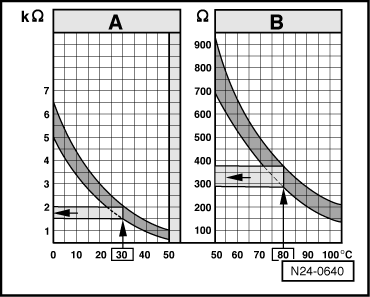
→ Scale A shows resistance values for temperature range 0...50 °C and scale B the values for temperature range 50...100 °C.

Examples:

  • ◆ 30 °C is in range A and corresponds to a resistance of 1.5...2.0 kω
  • ◆ 80 °C corresponds to a resistance from 275...375 ω
  • ‒ Reconnect connector.
 
N24-0671

If the specifications are not attained:

  • ‒ Replace engine control unit
    => Page 24-103 .

Continuation of check when display = ambient temperature:

  • ‒ → Pull 2 pin connector off intake air temperature sender -arrow-.
  • ‒ Remove intake manifold temperature sender (G72).
  • ‒ Reconnect connector.
  • ‒ Note intake air temperature figure in display zone 4.
  • ‒ Spray sender with commercial chilling agent whilst observing the temperature value. The temperature value must
         decrease.
  • ‒ Press the ⇒key.
  • ‒ Press keys 0 and 6 for the "End output" function and confirm input with the Q key.
  • ‒ Switch off ignition.

If the temperature figure in display zone 4 does not decrease:

  • ‒ Replace intake manifold temperature sender (G72)
    => Page 24-12 , item 5 .

Checking engine speed sender > < Checking coolant temperature sender