volkswagen Workshop Repair Guides

Volkswagen Workshop Service and Repair Manuals

Checking fuel pressure regulator and holding pressure > < Checking engine speed sender
Simos injection and ignition system
Checking components
Checking injectors

Special tools, workshop equipment, testers, measuring instruments and auxiliary items required

  • ◆ Test box V.A.G 1598/22
  • ◆ Hand multimeter V.A.G 1526 or multimeter V.A.G 1715
  • ◆ Diode test lamp V.A.G 1527
  • ◆ Adapter set V.A.G 1594
  • ◆ Current flow diagram

Check conditions

  • ● Engine speed sender must be OK, checking .
  • ● Fuel pump relay OK
 
N24-0588
  • ● → Fuse 32 must be OK.

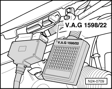
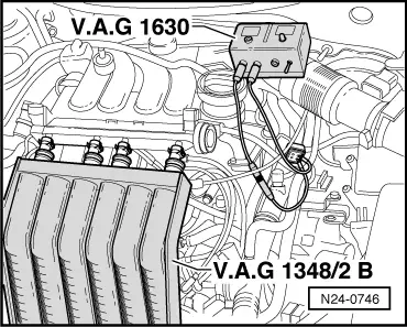
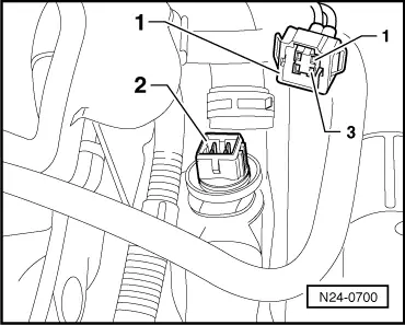
Checking activation and voltage supply

Warning!
Fuel system is under pressure! Before opening the system place a cloth around the connection. Then release pressure by carefully loosening the connection.
  • ‒ Remove intake manifold upper part
    .
  • ‒ Pull plug off all injectors.
 
A24-0090
  • ‒ → Connect diode test lamp V.A.G 1527 using aux. cables from V.A.G 1594 to connector contacts of Cyl. 1.
  • ‒ Operate the starter and check the voltage supply for No. 1 cylinder injector.
         The LED must flicker
  • ‒ Repeat check at the injector connectors for Cyls. 2...4.

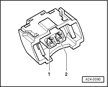
If the LED does not flicker on any cylinder:

 
A24-0090
  • ‒ → Connect diode test lamp to Cyl. 1 connector, contact 1 and earth.
  • ‒ Operate starter.
         The LED must light

If the LED does not light up:

  • ‒ Switch off ignition
  • ‒ Check wire between 2 pin connector contact 1 and fuel pump relay (J17) for open circuit using current flow diagram.
         Wire resistance: max. 1.5 ω

If the LED flickers on one or several cylinders:

 
N24-0709
  • ‒ → Connect test box V.A.G 1598/22 to wiring harness for control unit.
 
A24-0090
  • ‒ → Check wiring between test box and connector for open circuit according to current flow diagram.
         Injector 1: Contact 2+socket 73
         Injector 2: Contact 2+socket 80
         Injector 3: Contact 2+socket 58
         Injector 4: Contact 2+socket 65
         Wire resistance: Max.1.5 ω
  • ‒ Additionally check wires for short to one another.
         Specification: ∞ω
  • ‒ Check wiring between connector contacts 1 of injectors for open circuit to one another.
         Wire resistance: Max. 1.5 ω
 
A96-0134
  • ‒ If no fault is found in the activation or voltage supply, check resistance of injectors.

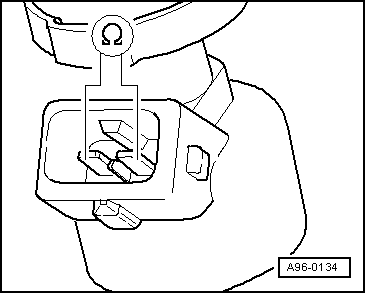
Checking resistance of injectors

  • ‒ → Check resistance of injectors individually
         Specification: 14...17 ω(at 20° C)

When the engine is warm the resistance will be approx. 4...6 ωhigher.

  • ‒ If the measured value is not as specified, renew the injector.

Checking spray pattern and for leaks

 
W00-0596
Warning!
Fuel system is under pressure! Before opening the system place a cloth around the connection. Then release pressure by carefully loosening the connection.

Special tools, workshop equipment, testers, measuring instruments and auxiliary items required

  • ◆ → Digital potentiometer V.A.G 1630
 
W00-0614
  • ◆ → Fuel-quantity comparison meter V.A.G 1348/2B

Test sequence

  • ‒ Remove intake manifold upper part
    => Page 24-16 .
 
N24-0746
  • ‒ Remove fuel rail complete with injectors.
  • ‒ → Hold injectors in the measuring appliance V.A.G 1348/2B.
 
N24-0700
  • ‒ → Pull 4 pin connector -1- off coolant temperature sender (G62) -2-.
 
N24-0746
  • ‒ → Set digital potentiometer V.A.G 1630 -side A- to 15 kωand using aux. cables from V.A.G 1594 connect to contacts 1+3 of disconnected plug.
  • ‒ Pull plug off ignition coils.
  • ‒ Operate starter (2nd person required). The injectors must pulsate and spray in accordance with firing order.
  • ‒ Switch off ignition and check injectors for leaks. No more than
         2 drops/min
    may leak from each injector.

Note:

When installing the injectors ensure that the O rings

are not damaged.

Checking fuel pressure regulator and holding pressure > < Checking engine speed sender