
Golf Mk4
| Assembly overview - trailing arm and transverse link |
 Note
Note| t | Never subject the wheel bearing to load when the drive shaft has been removed! |
| t | If the vehicle is to be placed on its wheels and moved, an outer joint from a drive shaft must be temporarily fitted. |
| t | It is not permitted to weld or straighten suspension parts which bear loads or locate the wheels. |
| t | Always renew self-locking nuts. |
| t | Always renew corroded nuts and bolts. |
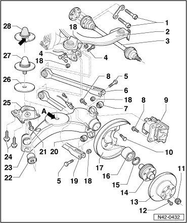
| 1 - | Multi-point socket head bolt, 40 Nm |
| 2 - | Subframe |
| q | Removing and installing → Chapter. |
| 3 - | Drive shaft |
| q | Pulling drive shaft out of wheel hub and pressing in ⇒ Removing and installing drive shafts → Chapter |
| 4 - | Hexagon bolt M 12 x 1.5 x 80 |
| q | Renew each time after removing. |
| q | Installation position has been changed: Bolt head faces opposite to direction of travel. |
| 5 - | Hexagon bolt M 12 x 1.5 x 75 |
| q | Renew each time after removing. |
| 6 - | Upper transverse link |
| q | Removing and installing → Chapter. |
| q | Various versions. |
| q | As of model year 2003, a transverse link with slot for adjusting camber is installed. |
| q | Allocation → Genuine parts catalogue. |
| 7 - | Ball joint |
| q | Check rubber boot for tears and damage. |
| q | Removing and installing → Chapter. |
| As of model year 2004, a bonded rubber bush is installed instead of the ball joint. |
| If the ball joint must be renewed, a new bonded rubber bush and a new upper transverse link → Item must also be installed. |
| The lower ball joint → Item and transverse link → Item must be renewed at the same time. |
| The ball joints have to be renewed with bonded rubber bushes on both sides of the vehicle! |
| Mixed installation is not permissible. |
| 8 - | Hexagon socket head bolt, 65 Nm |
| 9 - | Brake caliper |
| q | Repairing → Brake systems; Rep. Gr.47. |
| 10 - | Hexagon bolt, 10 Nm |
| 11 - | Self-locking 12-point nut |
| q | Tightening → Chapter. |
| q | Renew each time after removing. |
| 12 - | Cross-head screw, 4 Nm |
| 13 - | Brake disc |
| 14 - | Wheel hub with rotor for wheel speed sensor |
| q | Rotor is welded to wheel hub. |
| q | Removing and installing → Chapter. |
| 15 - | Retaining ring |
| q | Ensure proper seating. |
| 16 - | Wheel bearing |
| q | Renew, as it is destroyed when pressed out |
| q | Removing and installing → Chapter. |
| 17 - | Splash plate |
| 18 - | Self-locking nut |
| q | 70 Nm and turn 90° further. |
| q | Renew each time after removing. |
| 19 - | Lower transverse link |
| q | Removing and installing → Chapter. |
| q | Various versions. |
| q | As of model year 2003, a transverse link with slot for adjusting camber is installed. |
| q | Allocation → Genuine parts catalogue. |
| 20 - | Ball joint |
| q | Check rubber boot for tears and damage. |
| q | Removing and installing → Chapter. |
| As of model year 2004, a bonded rubber bush is installed instead of the ball joint. |
| If the ball joint must be renewed, a new bonded rubber bush and a new lower wishbone → Item must also be installed. |
| The upper ball joint → Item and transverse link → Item must be renewed at the same time. |
| The ball joints have to be renewed with bonded rubber bushes on both sides of the vehicle! |
| Mixed installation is not permissible. |
| 21 - | Hexagon bolt, 90 Nm |
| q | Renew each time after removing. |
| 22 - | Bonded rubber bush |
| q | Removing and installing → Chapter. |
| 23 - | Trailing arm |
| q | Removing and installing → Chapter. |
| q | Thread -arrow A- for mounting bump stop → Item has been discontinued as of 06.99. |
| q | If bump stop → Item is to be installed in a trailing arm produced prior to 06.99, thread -arrow A- must be drilled to 10.5 mm Ø. |
| 24 - | Hexagon bolt, 75 Nm |
| q | Renew each time after removing. |
| 25 - | Mounting bracket for rear axle |
| q | After installation, check total toe setting of rear axle and align if necessary. |
| q | Toe setting can be adjusted by moving mounting bracket |
| 26 - | Spacer |
| q | Fitted in vehicles with heavy-duty suspension only |
| 27 - | Bump stop with threaded stud |
| q | Tighten to 10 Nm. |
| q | No longer fitted as of 06.99. |
| q | Bump stop → Item is supplied as a replacement part. |
| 28 - | Bump stop with locating pin |
| q | Fitted as of 06.99. |
| q | Correct installation position is determined by the locating pin. |
| q | If fitted in vehicles produced prior to 06.99, locating pin must be cut off at the bottom. |
| q | The start of the spring coil must lie against the bar -arrow-. |
| q | Spring installation position → . |