| –
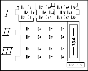
| Remove the contact from chamber 5 of the multi-pin connector III, -T8-, 8-pin, black, and insulate the removed wire. |
| –
| If a control wire for additional equipment i.e. power aerial or additional amplifier, is to be connected to this contact, then reconnect this wire to contact 17 on blue multi-pin connector I, part 3. |
| –
| Make a wiring connection from chamber 7 to chamber 5 on black 8-pin multi-pin connector III, -T8-. |
| This supplies chamber 5 with terminal 30. If this wiring connection is missing the radio unit will not work. |
|
|
|