volkswagen Workshop Repair Guides

Volkswagen Workshop Service and Repair Manuals

Electronic anti-theft system > < Overview of radio connectors
Contact assignment of the multi-pin connectors I, II, III on the rear of the radio
Multi-pin connector I, -T20- consists of 3 parts that are marked with different colours:
   
Multi-pin connector I, part 1, yellow
This connector is not used.
  N91-0160
Multi-pin connector I, part 2, green
7 - Telephone input signal, TEL+
11 - Remote control
12 - Telephone input signal, TEL-
  N91-0160
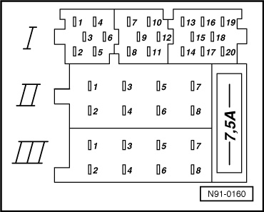
Multi-pin connector I, part 3, blue
13 - CD changer, DATA IN (data to radio)
14 - CD changer, DATA OUT (data from radio)
15 - CD changer, CLOCK (internal check protocol for data flow monitoring)
16 - CD changer, terminal 30 voltage supply, positive
17 - CD changer, control signal
18 - CD changer, left and right channels, audio signal earth
19 - CD changer, left audio signal channel, CD/L
20 - CD changer, right audio signal channel, CD/R
  N91-0160
Multi-pin connector II, -T8a-, 8-pin, brown
3 - Front right loudspeaker, positive
4 - Front right loudspeaker, negative
5 - Front left loudspeaker, positive
6 - Front left loudspeaker, negative
  N91-0160
Multi-pin connector III, -T8-, 8-pin, black
1 - Gala (speed dependant volume control)
2 - Muting (for telephone operation)
3 - Self-diagnosis, K wire
4 - Connection for ignition-key-controlled switching on and off (S-contact)
5 - Anti-theft system control signal, SAFE (terminal 30)
6 - Radio display illumination (terminal 58b)
7 - Battery positive (terminal 30)
8 - Battery negative (terminal 31)
  N91-0160

Electronic anti-theft system > < Overview of radio connectors