volkswagen Workshop Repair Guides

Volkswagen Workshop Service and Repair Manuals

Electronic anti-theft system > < Overview of radio connectors
Contact assignment of the multi-pin connectors I, II, III on the rear of the radio
   
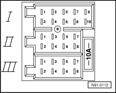
Multi-pin connector I, -T10-, 10-pin, red
1 - CD changer DATA IN (data to radio)
2 - CD changer, CLOCK IN (internal check protocol for data flow monitoring)
3 - CD changer voltage supply, negative, terminal 31 and LINE IN signal input earth
4 - CD changer DATA OUT (data from radio)
5 - CD changer LINE OUT signal output earth terminal 31, is not used
6 - CD changer voltage supply (+), terminal 30, (switched)
7 - CD changer LINE IN right
8 - CD changer LINE OUT left, is not used
9 - CD changer LINE OUT right, is not used
10 - CD changer LINE IN left
  N91-0112
Multi-pin connector II, -T8a-, 8-pin, brown
1 - Rear right loudspeaker, positive
2 - Rear right loudspeaker, negative
3 - Front right loudspeaker, positive
4 - Front right loudspeaker, negative
5 - Front left loudspeaker, positive
6 - Front left loudspeaker, negative
7 - Rear left loudspeaker, positive
8 - Rear left loudspeaker, negative
  N91-0112
Multi-pin connector III, -T8-, 8-pin, black
1 - Gala (speed dependant volume control)
2 - Muting (for telephone operation)
4 - Connection for ignition-key-controlled switching on and off (S-contact)
5 - Switched positive for electronically amplified roof aerial (not assigned)
6 - Radio display illumination (terminal 58b)
7 - Battery positive (terminal 30)
8 - Battery negative (terminal 31)
  N91-0112

Electronic anti-theft system > < Overview of radio connectors