
Golf Mk5
|
|
|
 Note
Note
|
|
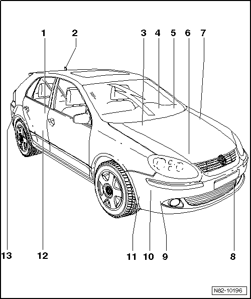
| 1 - | Fuel gauge sender -G- |
| q | Installation location: under rear bench seat, right. |
| q | Removing and installing → Rep. gr.20 |
| 2 - | Aerial for telephone, navigation system, auxiliary heating -R66- |
| q | For vehicles with auxiliary heater and remote control. |
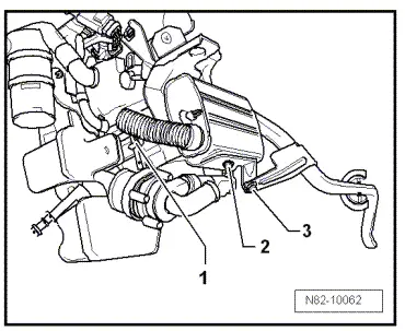
| 3 - | Heater coolant shut-off valve -N279- Golf ►2008 |
Note| The heater coolant shut-off valve -N279- is fitted only in vehicles with certain engines and with auxiliary heating. |
| q | Secured to engine compartment bulkhead |
| q | Removing and installing → Chapter |
| 4 - | Fresh air blower relay -J13- |
| q | Not in vehicles with Climatronic |
| q | Location: relay and fuse carrier below dash panel on left |
| q | Checking → Current flow diagrams, Electrical fault finding and Fitting locations |
| 5 - | Fuse carrier with auxiliary heater operation relay -J485- (only on vehicles with Climatronic) |
| q | Location: under dash panel on left → Current flow diagrams, Electrical fault finding and Fitting locations |
| 6 - | Coolant temperature sender -G62- |
| q | Location: on cylinder head connection |
| 7 - | Battery -A- |
| q | Location: in engine compartment on left |
| 8 - | Ambient temperature sensor -G17- |
| q | Checking: Vehicle diagnosis, testing and information system -VAS 5051B- or later model. |
| q | Removing and installing → Fig. |
| 9 - | Circulation pump -V55- |
| q | Location on auxiliary heater |
| q | Removing and installing → Chapter |
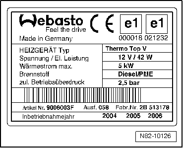
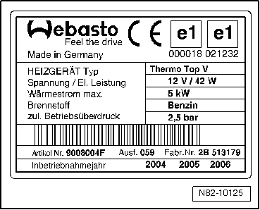
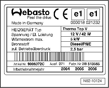
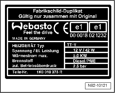
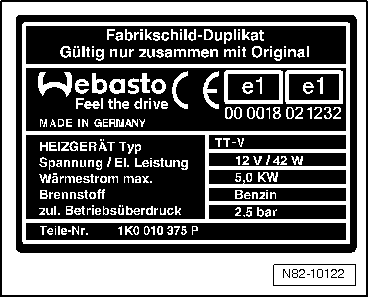
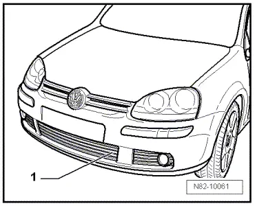
| 10 - | Auxiliary heater Thermo Top V |
| q | With auxiliary heating control unit -J364-. |
| q | Location: below front bumper on right |
| q | Removing and installing → Chapter |
| 11 - | Exhaust system |
| q | For auxiliary heating. |
| q | Removing and installing → Fig. |
| 12 - | Metering pump -V54- |
| q | Location: right side of fuel tank. |
| q | Fuel supply to auxiliary heater → Chapter. |
| q | It is possible that the metering pump ticks audibly but still does not deliver fuel because there is air in the intake. The control unit then switches it off completely. You should therefore read the fault memory using vehicle diagnosis, testing and information system -VAS 5051B- or later model, Self-diagnosis of Thermo Top V auxiliary heater. Erase fault memory and carry out final control diagnosis of Thermo Top V auxiliary heater. |
| q | Removing and installing → Chapter |
| q | Testing quantity of fuel delivered → Chapter |
| 13 - | Remote control receiver for auxiliary coolant heater -R149- |
| q | Removing and installing → Chapter |
|
|
|
|
|
|
|
|
|
|
|
|
|
|
 WARNING
 Caution