
Golf Mk5
| Electrical and electronic components and their locations |
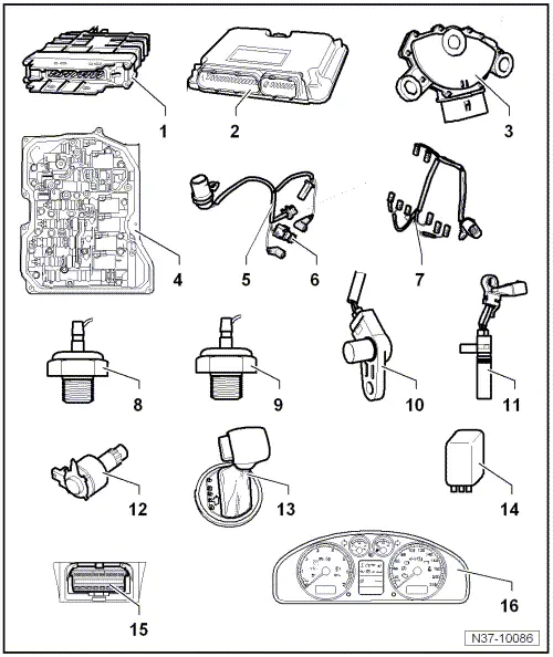
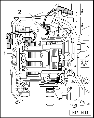
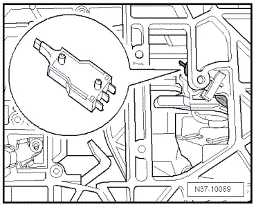
| 1 - | Control unit for automatic gearbox -J217- |
| q | The control unit transmits and receives data from the → data bus. |
| q | Location and removing and installing → Fig. |
| q | Can be checked using „guided fault finding“ of -VAS 5051- |
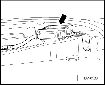
| 2 - | Engine control unit |
| q | The control unit transmits and receives data from the data bus |
| q | Location and removing and installing → Rep. Gr. 23 for the respective engine code letter → Rep. Gr. 24 for the respective engine code letter |
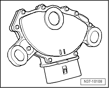
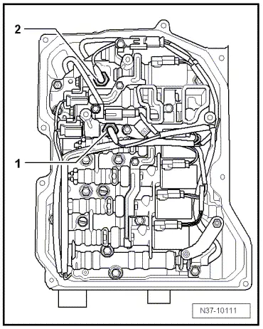
| 3 - | Multifunction switch -F125- |
| q | Location → Fig. |
| q | Can be checked using „guided fault finding“ of -VAS 5051- |
| q | Removing, installing and adjusting → Chapter. |
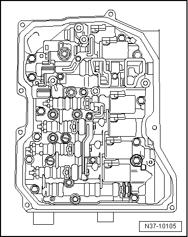
| 4 - | Valve body |
| q | Location → Fig. |
| q | Components can be checked using „guided fault finding“ of -VAS 5051- |
| q | Allocation → Electronic parts catalogue „ETKA“ |
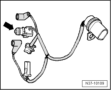
| 5 - | Wiring harness for sender |
| q | With gearbox oil temperature sender -G93- |
| q | Location → Fig. |
| q | Removing and installing → Chapter |
| q | Allocation → Electronic parts catalogue „ETKA“ |
| 6 - | Gearbox oil temperature sender -G93- |
| q | Location → Fig. |
| q | Can be checked using „guided fault finding“ of -VAS 5051- |
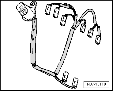
| 7 - | Wiring harness for solenoid valves |
| q | Location → Fig. |
| q | Removing and installing → Chapter |
| q | Allocation → Electronic parts catalogue „ETKA“ |
| 8 - | Automatic gearbox hydraulic pressure sender 1 -G193- |
| q | Not installed in all gearboxes |
| q | Allocation → Electronic parts catalogue „ETKA“ |
| q | Location → Fig. |
| 9 - | Automatic gearbox hydraulic pressure sender 2 -G194- |
| q | Not installed in all gearboxes |
| q | Allocation → Electronic parts catalogue „ETKA“ |
| q | Location → Fig. |
| 10 - | Gearbox input speed sender -G182- |
| q | Removing and installing → Chapter |
| q | Can be checked using „guided fault finding“ of -VAS 5051- |
| 11 - | Gearbox output speed sender -G195- |
| q | Removing and installing → Chapter |
| q | Can be checked using „guided fault finding“ of -VAS 5051- |
| 12 - | Selector lever lock solenoid -N110- |
| q | Location: selector lever lock solenoid is located in the selector mechanism. |
| q | Can be checked using „guided fault finding“ of -VAS 5051- |
| 13 - | Tiptronic switch -F189- |
| q | Location → Fig. |
| q | Can be checked using „guided fault finding“ of -VAS 5051- |
| 14 - | Terminal 50 voltage supply relay -J682- |
| q | In E box in engine compartment → Current flow diagrams, Electrical fault finding and Fitting locations. |
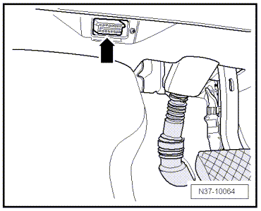
| 15 - | Diagnostic connection |
| q | Location → Fig. |
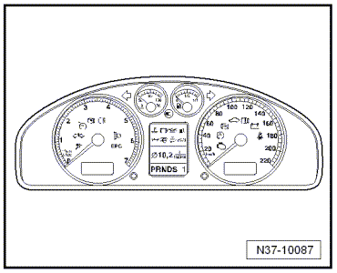
| 16 - | Selector lever position display -Y6- |
| q | Location → Fig. |
| q | Removing and installing → Electrical system; Rep. gr.90. |
|
|
|
|
|
|
|
|
|
|
|
|
|
|
|
|
|
|