Volkswagen Workshop Service and Repair Manuals
HOME
FEATURES
MENU
INDEX
ABOUT US
Installing >
< Removing and installing selector mechanism
Golf Mk5
Power transmission
6-speed manual gearbox 02Q
Gearbox mechanics,operation, construction,diff. / Repairing selector mechanism / moving_and_installing_selector_mechanism/">Removing and installing selector mechanism
Removing
Removing
Removing
Special tools and workshop equipment required
t
Torque wrench -V.A.G 1331-
t
Allocate grease using
→ Electronic parts catalogue (ETKA)
.
–
First check whether a coded radio is fitted. If so, obtain anti-theft code.
–
With ignition switched off, disconnect battery earth strap
→ Electrical system; Rep. gr.27
.
–
Remove gaiter with selector knob and noise insulation. Golf, Eos and Scirocco
→ Chapter
, Golf Plus
→ Chapter
, Passat, Passat CC and CC
→ Chapter
, Touran
→ Chapter
Golf 2004 ►, Scirocco and Eos
–
Remove securing bracket for centre console, remove footwell trim from centre console and ashtray or storage compartment for this
→ General body repairs, interior; Rep. gr.68
.
Golf 2009 ►
–
Remove ashtray or storage compartment and securing bracket for centre console
→ General body repairs, interior; Rep. gr.68
.
–
Remove rear footwell ducts, if fitted
→ Heater; Rep. gr.80
, remove centre console for this
→ General body repairs, interior; Rep. gr.68
.
Golf Plus
–
Remove upper parts and, if necessary, securing brackets for centre console
→ General body repairs, interior; Rep. gr.68
Touran
–
Remove ashtray or storage compartment from centre console
→ General body repairs, interior; Rep. gr.68
.
Vehicles where centre console securing brackets cannot be removed as a separate component:
–
Remove centre console,
→ General body repairs, interior; Rep. gr.68
.
Continuation for all
–
If present, remove interior monitoring sensor -G273- from rear securing nuts
→ Electrical system; Rep. gr.96
.
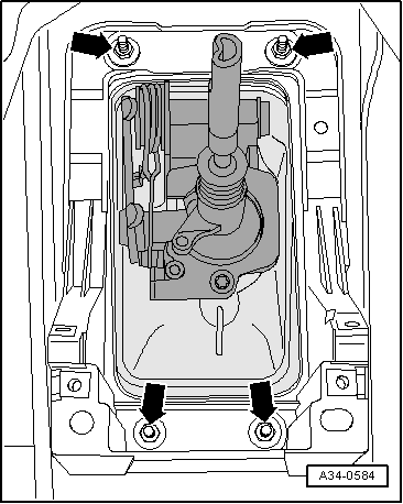
–
Remove nuts
-arrows-
for selector housing and centre console securing bracket.
–
Remove complete air filter housing if it is located over selector mechanism.
→ Rep. gr.23
or
→ Rep. gr.24
–
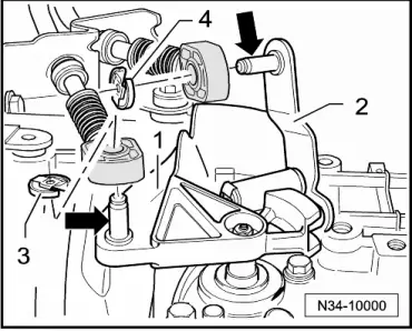
Remove circlip
-3-
for gear selector cable from gearbox selector lever
-1-
.
–
Pull gear selector cable off pin
-arrow-
.
Metal relay lever
–
Remove securing clip
-4-
for gate selector cable from relay lever
-2-
.
–
Pull gate selector cable off pin
-arrow-
.
Plastic relay lever
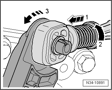
Releasing cable end-piece from gate selector cable
l
To avoid damage to gate selector cable, separate cable end-piece from gate selector cable before removal.
–
Pull locking mechanism forward to stop in
-direction of arrow 1-
and then lock by turning to left in
-direction of arrow 2-
.
–
Then push relay lever forwards (
-in direction of arrow 3-
).
–
Remove relay lever together with cable end-piece
→ Fig.
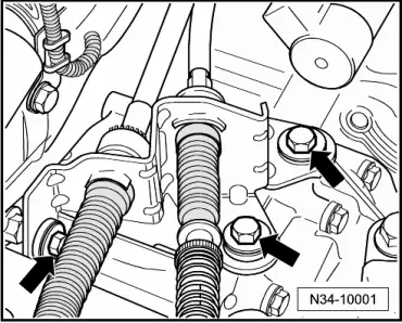
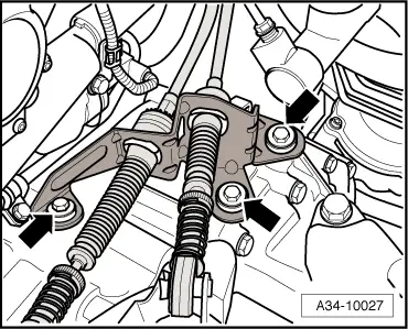
Continued for all selector mechanisms
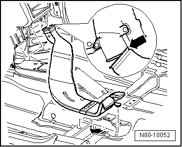
The cable support bracket is secured with either two bolts and a flange nut
-arrows-
,
or with three bolts
-arrows-
.
–
Remove noise insulation
→ General body repairs, exterior; Rep. gr.50
.
–
Remove tunnel cross members
→ Rep. gr.26
.
Vehicles with front-wheel drive
–
Remove underbody panels
→ General body repairs, exterior; Rep. gr.50
.
–
Disconnect front exhaust pipe at double clamp and remove from subframe
→ Rep. gr.26
.
–
Detach rear exhaust system and remove heat shield
→ Rep. gr.26
.
Vehicles with four-wheel drive
–
Unhook rear silencer from rubber mountings and remove rear section of exhaust system.
–
Remove front exhaust pipe
→ Rep. gr.26
.
–
Remove heat shield beneath propshaft.
–
Remove propshaft.
→ Rep. gr.39
–
Remove underbody panels
→ General body repairs, exterior; Rep. gr.50
.
Continuation for all
–
Swing selector housing down and remove with selector cables.
Power transmission
6-speed manual gearbox 02Q
Gearbox mechanics,operation, construction,diff. / Repairing selector mechanism / moving_and_installing_selector_mechanism/">Removing and installing selector mechanism
Removing
Installing >
< Removing and installing selector mechanism