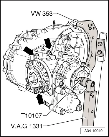
volkswagen Workshop Repair Guides

Volkswagen Workshop Service and Repair Manuals

Assembly order, gearbox "with” retaining ring A for input shaft sealing cover > < Removing
Installing
Installing
l  A new deep groove ball bearing has been pressed onto the input shaft → Item.
   
–  First insert input shaft -1- and 5th and 6th gear output shaft -2- together with selector rod -3-, selector fork -4- and reverse shaft -5-.
  N34-10030
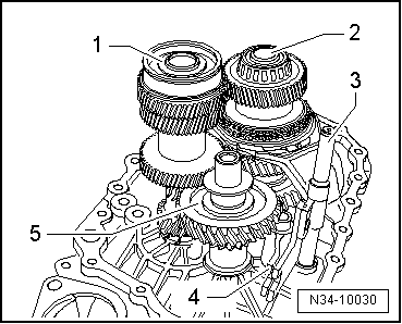
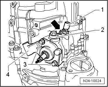
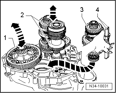
–  Then insert differential -1-.
  Note
A second mechanic will be required for further installation of shafts in clutch housing.
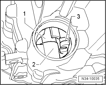
–  Take output shaft for 1st through 4th gears -3- with selector rods -4- in the right hand as shown in figure.
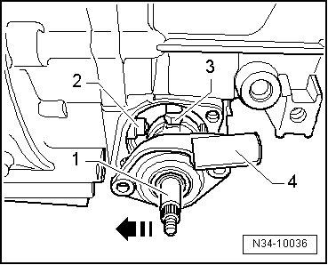
–  With the left hand, lift differential slightly.
–  At the same time, a 2nd mechanic must slightly lift input shaft and output shaft for 5th and 6th gears and reverse gear -2- together with reverse gear shaft.
–  Now insert output shaft for 1st through 4th gears in -direction of arrow-.
l  The teeth of the input shaft, the output shafts and the final drive input gear of differential must mesh.
–  Now, together with a second mechanic, place shafts and differential in their bearing seats.
  N34-10031
–  Secure support bridge -30-211A- for input shaft to clutch housing.
  Note
For clarity of illustration, clutch housing is shown turned 180°.
–  Screw in bolt -A- until input shaft rises slightly.
On some gearboxes, flats -A- are present on the deep groove ball bearing for the input shaft and the bearing support -B-.
  N34-10032
Check deep groove ball bearing for input shaft and gearbox housing.
  N34-11101
Deep groove ball bearing for input shaft and gearbox housing
No flats on deep groove ball bearing -A- or on bearing support -B- → Anchor
Flats on deep groove ball bearing -A- and on bearing support -B- → Fig.

From gearbox date 10 04 6 through around gearbox date 20 01 8:
A washer is installed above and one below the deep groove ball bearing for the input shaft → Item.
   
Upper washerOuter diameter78.6 mm
Lower washerOuter diameter85 mm

   
Measure distance above seat for deep groove ball bearing.
  N35-10149
Distance above deep groove ball bearingDimension “a”Upper washer
Through gearbox date 09 04 610 mmno
From gearbox date 10 04 610.7 mmyes

   
In the gearbox housing, the area below the seat for the deep groove ball bearing is also modified -arrow-.
  N35-10150
Area below bearing seatLower washer
Through gearbox date 09 04 6Not further machinedno
From gearbox date 10 04 6Machined slightly deeperyes

   
–  If necessary, lay a washer (outer diameter = 85 mm) -1- on deep groove ball bearing -2-.
  N34-10816
For some gearboxes:
Flats -A- on deep groove ball bearing for input shaft and on bearing support -B-
l  No washers may be laid above or below the deep groove ball bearing.
l  Flats -A- on deep groove ball bearing and on bearing support -B- in gearbox housing must line up.
–  Mark flats with coloured marks.
–  Transfer markings to upper area of deep groove ball bearing and to upper area of bearing support of gearbox housing (⇒ next figure).
–  Heat gearbox housing for about 10 minutes to 100° C in vicinity of seat for deep groove ball bearing of input shaft using -hot air blower-, e.g. -V.A.G 1416-.
  Note
t  Heating is necessary to avoid damage to deep groove ball bearing when gearbox housing is installed.
  N34-11101
t  Line up marking on deep groove ball bearing -A- with marking on gearbox housing -B- and set gearbox housing in place.
–  For all gearboxes, heat gearbox housing for about 10 minutes to 100° C in vicinity of seat for deep groove ball bearing of input shaft using -hot air blower-, e.g. -V.A.G 1416-.
–  Apply sealant -AMV 188 200 03- evenly to sealing surface of clutch housing.
  N34-11102
–  Set gearbox housing in place and tighten new bolts -A-, -B- and -C- to specified torque.
Allocation of bolts:
A - Bolt with captive washer
B - Bolt without washer
C - Bolt with captive washer
  N34-10565
–  If a washer was laid on the deep groove ball bearing before the gearbox housing was set in place, a washer -1- (outer diameter = 78.6 mm) must also be placed above the deep groove ball bearing -2-. → Anchor
  N34-10817
–  Install retaining ring -1- for deep groove ball bearing of input shaft.
–  Remove support bridge -30-211A- for input shaft.
–  If stop sleeve for selector shaft has been removed, now drive it in to stop of tool → Fig..
–  Turn gearbox in repair stand with opening for selector shaft upwards.
  N34-10033
–  Insert selector shaft -1- in lower bearing -2- and in selector forks -3-.
  Note
For better clarity, sealing cover is removed in illustration.
  N34-10035
–  Now press selector shaft -1- against stop sleeve -2- in -direction of arrow- and guide downwards with selector finger -3- through selector forks to stop.
l  Selector shaft cover -4- must be parallel to bolting surface on gearbox housing.
l  Selector shaft must move freely in gate selection direction (upwards and downwards).
  Note
If selector shaft cover is tilted relative to bolting surface, selector shaft is not inserted in lower bearing.
  N34-10036
–  Tighten bolts -3- for selector shaft cover -4-.
–  Screw in locking bolt -2-, ensuring that angled rod -arrow- is not engaged.
–  Install reversing light switch -F4--1-.
  N34-10024
–  Install flange shaft.
  A39-0360
–  Drive in input shaft oil seal flush.
–  Install slave cylinder with release bearing → Chapter.
–  Shift through all gears.
  N34-1017
–  Drive sealing cover into gearbox housing to stop using thrust piece -T10042-.
Attach bevel box to gearbox as follows:
–  Grease splines of differential with grease for clutch plate splines -G 000 100-.
–  Push bevel box completely onto gearbox, ensuring that splines of bevel box input shaft and differential are centred when brought together.
–  Align splines of right flange shaft and differential bevel gear, turning flange shaft if necessary.
–  If splines are correctly positioned and shafts are centred, then bevel box will slide to stop against gearbox.
  Note
Do not use securing bolts to pull bevel box onto gearbox, or bevel box will cant and bolt holes can break off.
  N34-10037
–  Tighten the 4 connecting bolts -arrows- for bevel box to gearbox (only 3 are visible in figure).
–  Tighten right flange shaft countersunk bolt with socket -T10107-.
–  Install gearbox → Chapter.
  A34-10040

Assembly order, gearbox "with” retaining ring A for input shaft sealing cover > < Removing