volkswagen Workshop Repair Guides

Volkswagen Workshop Service and Repair Manuals

Torque settings > < Removing bevel box
Installing bevel box
Install in the reverse order of removal, observing the following:
–  With gearbox installed, grease splines of differential with grease for clutch plate splines -G 000 100-.
   
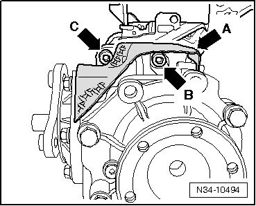
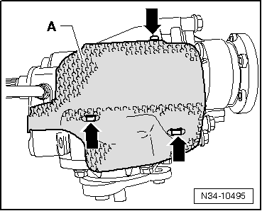
–  If bevel box is to be renewed, install heat shield -A- as needed.
–  Tighten bolts -arrows- to 5 Nm.
–  Carefully pull the flange shaft out of the bevel box; (oil seal for flange shaft is not allowed to be damaged).
–  Push bevel box completely onto gearbox, ensuring that splines of bevel box input shaft and differential are centred when brought together.
–  If splines are correctly positioned and shafts are centred, then bevel box will slide to stop against gearbox.
  N34-10495
A heat shield -arrow A- is installed on top of bevel box of some gearboxes.
–  The upper bolts for securing bevel box to gearbox are accessible as follows:
Bolt -arrow B- is accessible from beneath heat shield.
Bolt -arrow C- is accessible from above heat shield.
  Note
Do not use securing bolts to pull bevel box onto gearbox, or bevel box will cant and bolt holes can break off.
  N34-10494
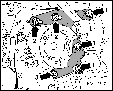
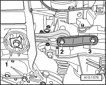
–  Bolt bevel box carrier to engine and bevel box, observing tightening sequence of bolts -arrows 1-, -arrows 2- and -arrow 3- → Chapter.
t  Shortly after start of production, the heads of bolts -arrows 2- were matched to the other bolts
–  Install particle filter with support. → Rep. Gr.26
–  Screw on cooler for exhaust gas recirculation. (Do not open cooling system) → Rep. Gr.26
–  If present, install support for exhaust system → Rep. Gr.26.
–  Install support for turbocharger → Rep. Gr.21
–  Insert the right flange shaft, turning the flange shaft if necessary.
–  Bolt on flange shaft → Item.
–  Attach right drive shaft to gearbox → Running gear, axles, steering; Rep. Gr.40.
  N34-10717
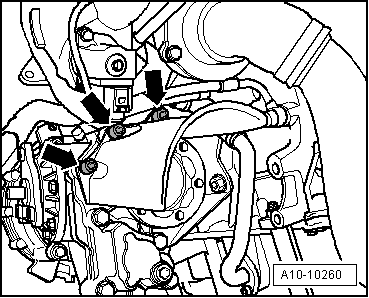
–  If present, attach shield for right drive shaft to bevel box -arrows- and tighten to specified torque → Chapter.
–  Install subframe and suspension links → Running gear, axles, steering; Rep. Gr.40.
  A10-10260
–  Press engine/gearbox assembly towards bulkhead, carefully guiding bevel box pin into propshaft flange.
  Note
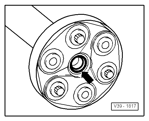
t  When removing and installing gearbox, do not damage seal in the propshaft flange -arrow-. Renew propshaft if damaged.
t  Ensure that propshaft is horizontal when pushing onto guide pin.
  V39-1817
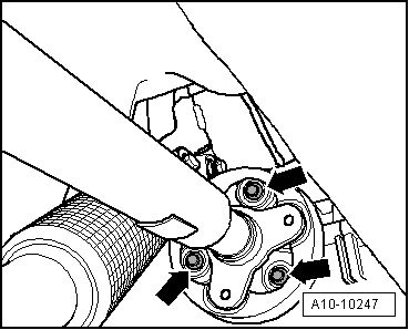
–  Bolt propshaft with flexible coupling to bevel box flange -arrows- → Rep. Gr.39.
  Note
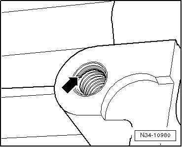
t  From gearbox manufacture date 28 05 7, there are threaded inserts (e.g. “HeliCoil”) in the bolting holes for the pendulum support.
  A10-10247
t  Identification: shoulder along beginning of thread -arrow-.
t  Ensure that the correct securing bolts and torque specifications are used. → Running gear, axles, steering; Rep. Gr.40
  N34-10980
–  Attach pendulum support to gearbox, bolt -2- and bolt -3- → Running gear, axles, steering; Rep. Gr.40.
–  Assemble exhaust system and attach exhaust system bracket to subframe → Rep. Gr.26.
–  Check gear oil in bevel box → Chapter.
–  Check gear oil in gearbox → Chapter.
–  Install noise insulation → General body repairs, exterior; Rep. Gr.50.
  A10-1578
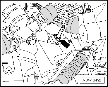
–  Screw breather pipe -arrow-, if present, into bevel box and tighten to 10 Nm.
If selector mechanism was removed from gearbox
–  Assemble and adjust selector mechanism → Chapter.
–  Install complete air filter housing → Rep. Gr.23.
–  Check headlight adjustment of vehicles with -front vehicle level sender- → Electrical system; Rep. Gr.94.
  N34-10492

Torque settings > < Removing bevel box