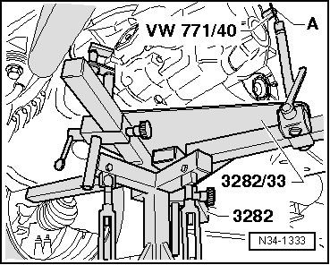
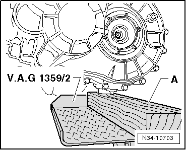
volkswagen Workshop Repair Guides

Volkswagen Workshop Service and Repair Manuals

Torque settings > < Removing gearbox
Installing gearbox
Installing gearbox
  Note
Refer to procedure “Removing gearbox” for required special tools → Chapter.
  Note
t  When performing repair work, renew self-locking nuts and bolts.
t  Renew bolts which must be tightened to a torque angle.
t  All cable ties which were opened or cut during removal must be renewed at the same points.
t  
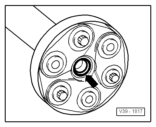
Clean input shaft splines and, on used clutch plates, clean hub splines; remove corrosion and apply only a very thin coat of clutch plate spline grease -G 000 100- to splines. Then move clutch plate to and fro on input shaft until hub moves freely on shaft. Remove excessive grease.
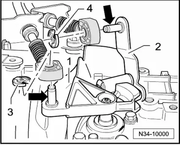
–  If the gearbox is to be renewed, the gearbox selector lever and relay lever must be transferred to the new gearbox.
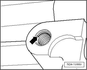
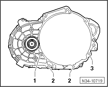
–  All threaded holes into which self-locking bolts are to be screwed must be cleaned of residual locking fluid using a thread chaser.
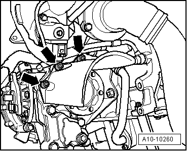
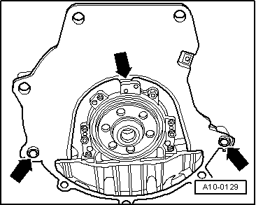
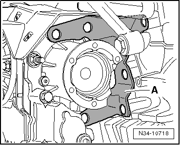
–  Check whether dowel sleeves for aligning engine and gearbox are fitted in cylinder block and install if necessary.
If dowel sleeves are not fitted, difficulties shifting gears, clutch problems and possible noises from the gearbox (rattling of gears which are not engaged) could occur.
   
–  Ensure that intermediate plate is hooked into sealing flange and pushed onto dowel sleeves -arrows-.
–  Check release bearing for wear. If necessary, renew slave cylinder with release bearing → Chapter.
To install gearbox “02Q four-wheel drive”, set up gearbox support -3282- with adjustment plate -3282/33-.
–  Align arms of gearbox support according to holes in adjustment plate.
  A10-0129
–  Attach support elements-A- to adjustment plate as illustrated.
–  Screw in pin -3282/29- instead of support element-C-.
–  Place gearbox on engine and gearbox jack -V.A.G 1383 A-.
–  Align adjustment plate and gearbox parallel to one another.
–  Screw pin -3282/29- into hole on gearbox for securing bolt of pendulum support.
  N34-1332
–  Secure adapter -VW 771/40- in threaded hole of gearbox housing as shown in figure.
–  Secure gearbox to gearbox support -3282- using bolt (M10x20) -A-.
–  Position engine and gearbox jack -V.A.G 1383 A- under vehicle. Arrow on adjustment plate points in direction of vehicle travel.
–  Raise gearbox in vicinity of bevel box differential using spindles of gearbox support -3282-.
  Note
t  When installing gearbox, observe electromechanical steering box.
t  Be careful of all lines when installing gearbox.
Vehicles with particle filter
  N34-1333
–  Set bevel box carrier -A- on bevel box.
Continuation for all
–  Align gearbox to engine and join.
  N34-10718
–  Screw in engine/gearbox connecting bolts -1...3- and tighten to specified torque → Chapter.
–  After bottom of gearbox and engine are bolted together, remove gearbox support -3282- from gearbox.
–  Install gearbox selector lever on selector shaft of gearbox and tighten hexagon nut to specified torque → Item.
Metal relay lever
  N34-10719
–  Insert relay lever -1- and clip in securing clip -arrow-.
  N34-10012
Plastic relay lever
–  Insert relay lever together with cable end-piece.
l  Catch -arrow 1- secures relay lever.
l  Ensure proper engagement.
l  Cable end-piece must be located behind catch -arrow 2-.
Continuation for all
  N34-10903
–  Install bracket on gearbox using new hexagonal bolts -arrows- and tighten to specified torque → Chapter.
  A10-1683
–  Align engine and gearbox in installation position. Do this by tightening spindles of support bracket -10 - 222 A- until bracket -1- contacts gearbox mounting -2-.
  N34-10009
–  Also position engine and gearbox jack -V.A.G 1383 A- with universal support -V.A.G 1359/2- under gearbox near differential and raise until gearbox bracket is parallel to gearbox mounting.
A - Wooden block
  Note
t  Use stepladder -VAS 5085- to install bolts.
t  To prevent damage to threads in bracket, gearbox mounting and bracket must be parallel to each other.
  N34-10703
–  Screw new hexagon bolts -arrows- for gearbox mounting -2- into bracket -1- and tighten to specified torque → Chapter.
  WARNING
Do not remove support bracket -10-222 A- until all bolts securing the assembly mounting have been tightened to specified torque.
  Note
Install engine and gearbox mounting free of tension → Rep. Gr.10.
Vehicles without particle filter
  N34-10009
–  Bolt bevel box carrier to engine and bevel box, observing tightening sequence of bolts -arrows 1- and -arrows 2- → Chapter.
–  Then bolt turbocharger oil return line -A- to engine → Rep. Gr.21.
  N34-10505
–  Install support -A- for exhaust manifold, if present → Rep. Gr.26.
  N34-10522
Vehicles with particle filter
–  Bolt bevel box carrier to engine and bevel box, observing tightening sequence of bolts -arrows 1-, -arrows 2- and -arrow 3- → Chapter.
–  Install support for particle filter → Rep. Gr.26.
Continuation for all
  N34-10717
–  Install small cover plate -A- behind bevel box, if present -arrow-.
–  Attach left and right drive shafts to gearbox → Running gear, axles, steering; Rep. Gr.40.
  N34-1121
–  If present, attach shield for right drive shaft to bevel box -arrows- and tighten to specified torque → Chapter.
–  Install subframe and suspension links → Running gear, axles, steering; Rep. Gr.40.
  A10-10260
–  Press engine/gearbox assembly towards bulkhead, carefully guiding bevel box pin into propshaft flange.
  Note
t  When removing and installing gearbox, do not damage seal in the propshaft flange -arrow-. Renew propshaft if damaged.
t  Ensure that propshaft is horizontal when pushing onto guide pin.
  V39-1817
–  Bolt propshaft with flexible coupling to bevel box flange -arrows- → Rep. Gr.39.
  Note
t  From gearbox manufacture date 28 05 7, there are threaded inserts (e.g. “HeliCoil”) in the bolting holes for the pendulum support.
  A10-10247
t  Identification: shoulder along beginning of thread -arrow-.
t  Ensure that the correct securing bolts and torque specifications are used. → Running gear, axles, steering; Rep. Gr.40
  N34-10980
–  Attach pendulum support to gearbox, bolt -2- and bolt -3- → Running gear, axles, steering; Rep. Gr.40.
–  Assemble exhaust system and attach exhaust system bracket to subframe → Rep. Gr.26.
  A10-1578
–  Fit charge air hose → Rep. Gr.21.
–  Insert upper engine/gearbox securing bolts and tighten to torque specification → Chapter.
  N34-10524
–  Screw breather pipe -arrow-, if present, into bevel box and tighten to 10 Nm.
–  Install starter and attach connector and wiring to starter → Electrical system; Rep. Gr.27.
  N34-10492
–  Attach earth strap -1- to upper starter bolt.
–  Push connector -2- onto reversing light switch -F4-.
–  Push pipe/hose line or plastic line -A- to stop into slave cylinder breather and press down clip -arrow-.
  N34-10003
–  Test line by tugging on it.
–  Remove hose clamp -3094- from pipe/hose line or supply hose.
–  After removing hose clamp -3094-, return supply hose to its original position, if necessary.
–  Bleed clutch system → Chapter.
  N34-10002
–  Bolt selector cable support brackets to gearbox and tighten bolts and nuts -arrows- to specified torque → Item and → Item.
  N34-10001
–  Spread a small amount of grease -G 000 450 02- on pins -arrow- of gearbox selector lever -1-.
–  Renew securing clip -3- each time it is removed.
Metal relay lever
–  Spread a small amount of grease -G 000 450 02- on pins -arrow- of relay lever -2-.
–  Push gate selector cable onto respective pins -arrow- and secure with securing clip -4-.
Plastic relay lever
–  Insert gate selector cable in cable end-piece.
Continuation for all
–  Adjust selector mechanism → Chapter.
–  If necessary, install engine cover.
–  If removed, install complete air filter housing → Rep. Gr.23.
–  Connect battery and follow procedure after connecting battery → Electrical system; Rep. Gr.27.
–  Check gear oil in gearbox → Chapter.
–  Check gear oil in bevel box → Chapter.
–  Install lower part of front left wheel housing liner → General body repairs, exterior; Rep. Gr.66.
–  Install noise insulation → General body repairs, exterior; Rep. Gr.50.
–  Install wheels → Running gear, axles, steering; Rep. Gr.44.
–  For vehicles with front sender for vehicle level, check headlight adjustment → Electrical system; Rep. Gr.94.
  N34-10000

Torque settings > < Removing gearbox