
Golf Mk5
| Dismantling and assembling input shaft |

| Special tools and workshop equipment required |
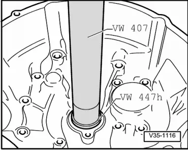
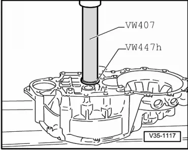
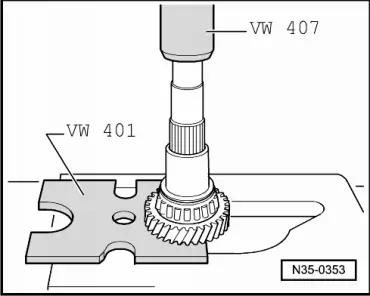
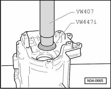
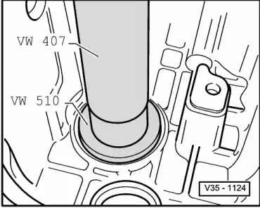
| t | Press tool -VW 407- |
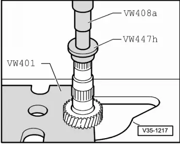
| t | Thrust pad -VW 447 H- |
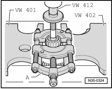
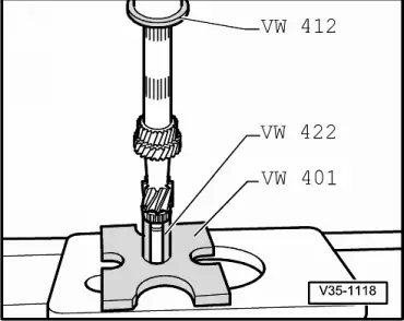
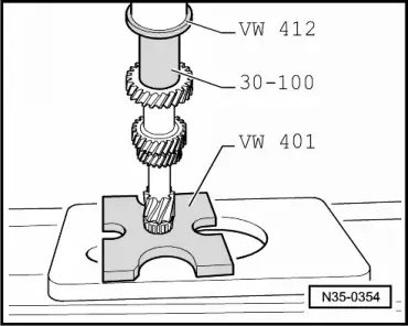
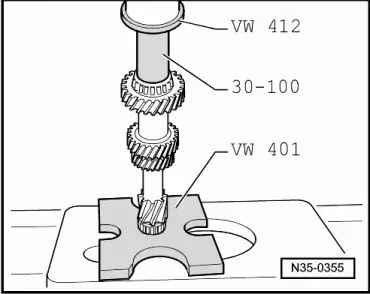
| t | Press tool -VW 412- |
| t | Tube -VW 422- |
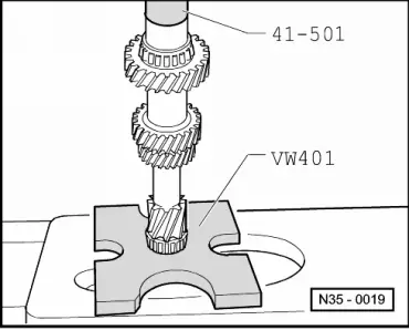
| t | Pressure plate -VW 401- |
| t | Pressure plate -VW 402- |
| t | Press tool -VW 408 A- |

| t | Drift sleeve -41 - 501- |
| t | Thrust pad -VW 447 i- |
| t | Drift sleeve -30 - 100- |
| t | Thrust pad -VW 510- |
| t | Splitter -3 - Kukko 17/1- |
|
|
|
|
|
|
|
|
|
|
|
|
|

|
|
|
|
|
|
|
|
|
|
|
|
|
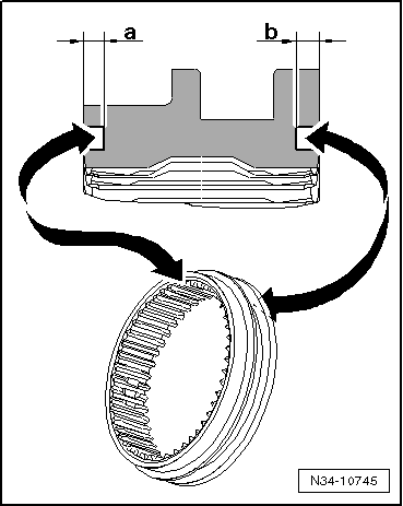
| Dimension -a- (6th gear side) | Through gearbox date 11 06 6 | From gearbox date 12 06 6 |
| 1.5 mm | 1.8 mm |
| Dimension -b- (5th gear side) | Through gearbox date 11 06 6 | From gearbox date 12 06 6 |
| 1.5 mm | 2.0 mm |
|
 Note
Note
|
|
|
|
|
|