
Golf Mk5
| Dismantling and assembling input shaft |

| Special tools and workshop equipment required |
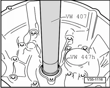
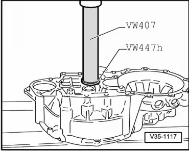
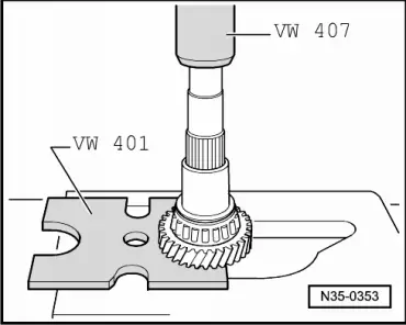
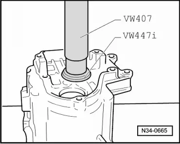
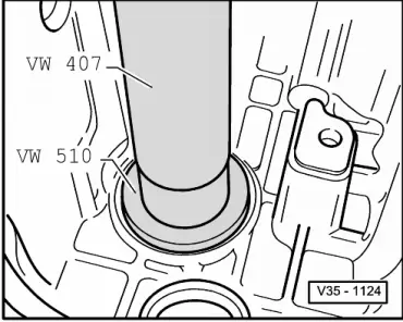
| t | Press tool -VW 407- |
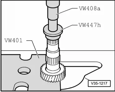
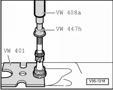
| t | Thrust pad -VW 447 H- |
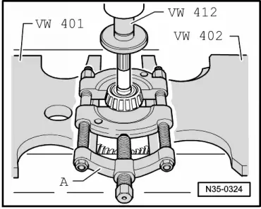
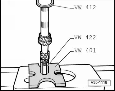
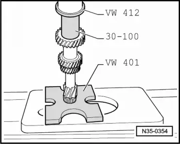
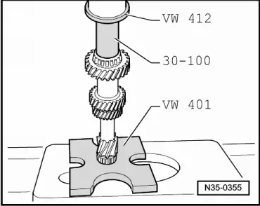
| t | Press tool -VW 412- |
| t | Tube -VW 422- |
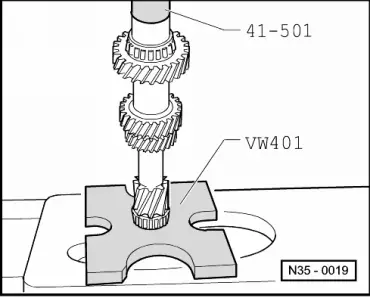
| t | Thrust plate -VW 401- |
| t | Thrust plate -VW 402- |
| t | Press tool -VW 408 A- |

| t | Drift sleeve -41 - 501- |
| t | Thrust pad -VW 447 i- |
| t | Drift sleeve -30 - 100- |
| t | Thrust pad -VW 510- |
| t | Splitter -3 - Kukko 17/1- |
 Note
Note| t | When installing new gears, refer to → Electronic parts catalogue “ETKA” and technical data → Chapter. |
| t | If the position of the tapered roller bearings is affected when parts are exchanged, the input shaft must be readjusted. See adjustment overview → Chapter. |

| 1 - | Clutch housing |
| 2 - | Tapered roller bearing outer race |
| q | Pressing out → Fig. |
| q | Pressing in → Fig. |
| 3 - | Tapered roller bearing inner race |
| q | Pressing off → Fig. |
| q | Pressing on → Fig. |
| 4 - | Input shaft |
| q | Adjusting → Chapter |
| 5 - | Gear wheel for 3rd gear |
| q | Installation position: shoulder faces 4th gear |
| q | Pressing off → Fig. |
| q | Pressing on → Fig. |
| 6 - | Retaining ring |
| q | Always renew |
| 7 - | Gear wheel for 4th gear |
| q | Pressing off with tapered roller bearing outer race and sleeve → Fig. |
| q | Pressing on → Fig. |
| q | Collar faces 3rd gear |
| 8 - | Tapered roller bearing inner race |
| q | Pressing off with gear wheel and sleeve for 4th gear → Fig. |
| q | Pressing on → Fig. |
| 9 - | Thrust washer |
| 10 - | Tapered roller bearing outer race |
| q | Pressing out → Fig. |
| q | Pressing in → Fig. |
| 11 - | Shim |
| q | Determining thickness → Chapter |
| 12 - | Gearbox housing |
| 13 - | Sleeve |
| q | For needle bearing |
| q | Press off with gear wheel for 4th gear and tapered roller bearing inner race → Fig. |
| q | Pressing on → Fig. |
| q | Set thrust washer → Item in place before installing |
| 14 - | Needle bearing |
| 15 - | Synchromeshed gear for 5th gear |
| 16 - | Wave spring washer |
| q | From gearbox date 26 05 8 |
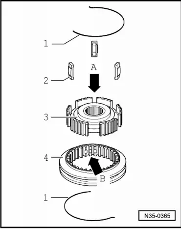
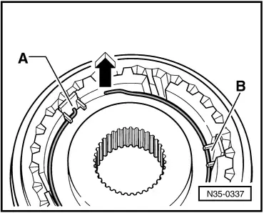
| q | In this case, install only locking piece springs without angled ends. (As shown in → Fig. - item 1-) |
| q | Allocate according to → Electronic parts catalogue “ETKA” |
| 17 - | Synchro-ring for 5th gear |
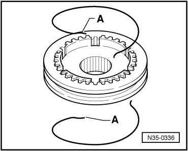
| q | With cast locking pieces → Fig. |
| q | Check for wear → Fig. |
| 18 - | Locking collar with synchro-hub for 5th and 6th gears |
| q | Pull off individually → Chapter |
| q | Pull off together with gearbox housing → Chapter |
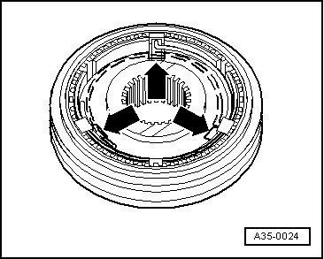
| q | Dismantling and assembling → Fig. and → Fig. |
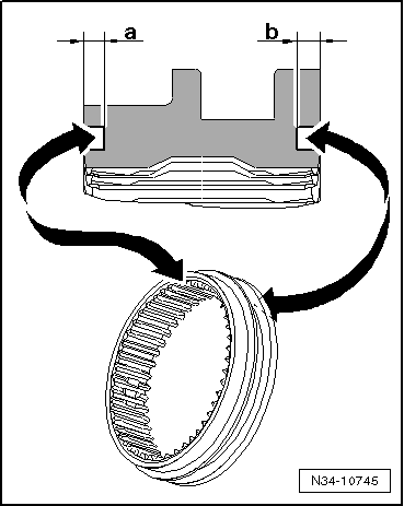
| q | From gearbox date 12 06 6, locking collar modified → Item |
| q | Adjusting 5th and 6th gears, from gearbox date 12 06 6 → Fig. |
| q | Adjusting 5th and 6th gears, through gearbox date 11 06 6 → Fig. |
| q | Installation of springs with angled ends for locking pieces → Fig. |
| 19 - | Synchro-ring for 6th gear |
| q | With cast locking pieces → Fig. |
| q | Check for wear → Fig. |
| 20 - | Wave spring washer |
| q | From gearbox date 26 05 8 |
| q | In this case, install only locking piece springs without angled ends. (As shown in → Fig. - item 1-) |
| q | Allocate according to → Electronic parts catalogue “ETKA” |
| 21 - | Synchromeshed gear for 6th gear → Item |
| 22 - | Needle bearing → Item |
| q | For 6th gear |
| q | Renew together with sleeve |
| 23 - | Sleeve → Item |
| q | For 6th gear needle bearing |
| q | Renew together with needle bearing |
| 24 - | Thrust washer |
| q | Through gearbox date 20 08 6 |
| 25 - | Cylindrical roller bearing inner race |
| q | Allocation → Fig. |
| q | Through gearbox date 20 08 6 |
| q | Mark before removing |
| q | Do not interchange with inner race for cylinder roller bearing of output shaft |
| 26 - | Inner race for cylindrical roller bearing with thrust washer |
| q | Allocation → Fig. |
| q | For input shaft |
| q | From gearbox date 21 08 6 |
| 27 - | Bolt → Item |
| q | Allocation → Fig. |
| q | Self-locking |
| q | Always renew |
|
|
|
|
|
|
|
|
|
|
|
|
|
|
|
|
|
|
|
|
|
|
|
|
|
|
| Dimension -a- (6th gear side) | Through gearbox date 11 06 6 | From gearbox date 12 06 6 |
| 1.5 mm | 1.8 mm |
| Dimension -b- (5th gear side) | Through gearbox date 11 06 6 | From gearbox date 12 06 6 |
| 1.5 mm | 2.0 mm |
|
Note
|
|
|
|
|
|