volkswagen Workshop Repair Guides

Volkswagen Workshop Service and Repair Manuals

Specified torques > < Removing
Installing
Installing
Install in the reverse sequence, noting the following:
–  Align selector housing parallel to body.
l  Distance to body must be same on both sides.
Secure selector housing → Item or → Item.
   
–  Route cables -1- from selector mechanism -2- to gearbox as follows:
l  Cables must lie parallel to each other and must not cross.
l  Cables must be laid in the intended indentation in heat shield -3-.
  A34-0610
Clip -A- holds cables and heat shield together in position.
The holes in the cable end-pieces have different diameters.
Allocation of cable end-pieces → Fig.
–  Spread a small quantity of grease on pins of gearbox selector lever -1- and relay lever -2-.
  N34-11247
Allocate grease using → Electronic parts catalogue (ETKA).
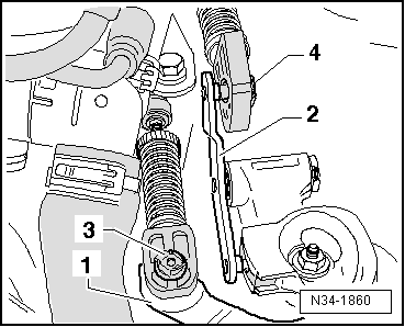
–  Renew securing clip -3- and, for metal relay lever, securing clip -4- each time they are removed.
–  Secure gear selector cable with securing clip -3- and gate selector cable with securing clip -4-.
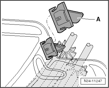
Cable end-piece to plastic relay lever
–  Fit relay lever and cable end-piece together → Chapter.
–  Insert gate selector cable in cable end-piece.
Continued for all selector mechanisms
–  Install centre console → General body repairs, interior; Rep. gr.68.
–  Remove gaiter with gear knob and noise insulation. Golf → Chapter, Golf Plus → Chapter
–  Install underbody panels → General body repairs, exterior; Rep. gr.50.
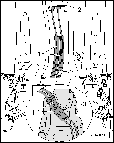
–  Assemble exhaust system free of tension and attach tunnel cross-piece → Rep. gr.26.
Adjust selector mechanism → Chapter.
–  Install, if necessary, complete air filter housing → Rep. gr.23 or → Rep. gr.24.
–  Follow procedure after connecting battery → Electrical system; Rep. gr.27.
  N34-1860

Specified torques > < Removing