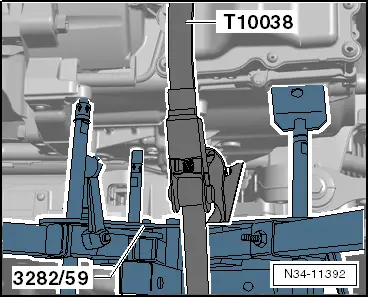
| t
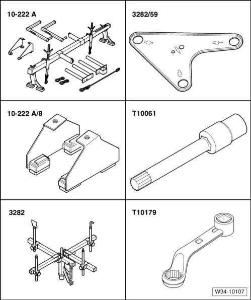
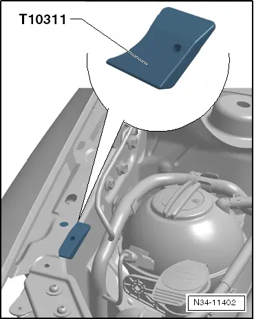
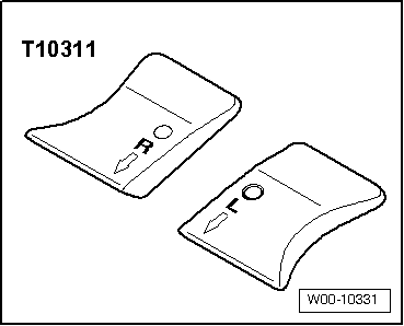
| Golf Plus only: wing support -T10311- |
| t
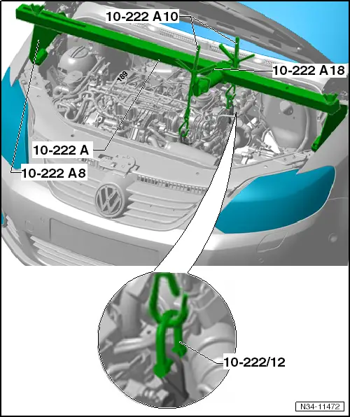
| Not illustrated: Engine and gearbox jack -V.A.G 1383 A- |
| The gearbox is removed downwards separately, without engine. »From above« |
| Remove battery, air filter and starter. |
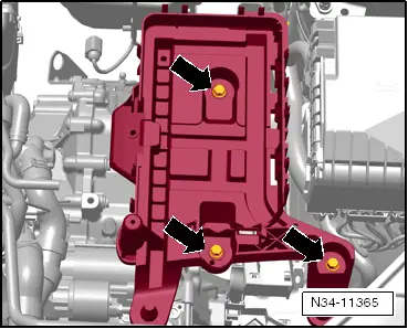
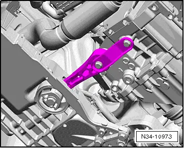
| Remove noise insulation beneath engine, lower cover in front left wheel housing and pendulum support. |
| –
| Raise vehicle. All 4 supports of lifting platform must be at same height. |
| –
| Move selector lever to position »P« position. |
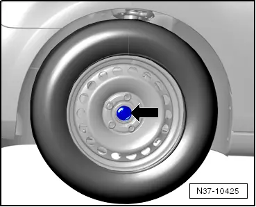
| Only in vehicles with stub shafts |

Note | After loosening centre bolt, do not lower vehicle to ground again. |
|
|
|