volkswagen Workshop Repair Guides

Volkswagen Workshop Service and Repair Manuals

Removing and installing cylinder head > < Removing and installing toothed belt (vehicles with engine support bolted close to engine)
Removing and installing toothed belt (vehicles with engine support bolted further away from engine)
   
Removing and installing toothed belt (vehicles with engine support bolted further away from engine)
  Note
t  A revised engine support has been introduced gradually and it is no longer necessary to remove the engine support and to support the engine for the procedure „removing, installing and tensioning toothed belt“.
t  To change the tensioning roller, for both versions the engine support must be removed.
Special tools and workshop equipment required
t  Diesel injection pump locking pin -3359-
t  Locking pin -T10060 A-
t  Crankshaft stop -T10100-
t  Counterhold tool -T10172-
t  Special wrench, long reach -T10264-
t  Locking tool -T10265-

Removing
–  Remove engine cover. → Fig. To do this, pull engine cover upwards abruptly at front -arrows A- and then pull forwards out of rear fastening -arrow B-.
   
–  Remove two-piece engine cover panel → Fig..
  WARNING
t  In extreme cases the fuel lines and the fuel can reach a temperature of 100 °C on vehicles with unit injector engine. Allow the fuel to cool down before disconnecting the lines - danger of scalding.
t  Wear protective gloves.
t  Wear eye protection.
  N10-10000
–  Pull fuel supply hose -1- and fuel return hose -2- off fuel lines.
–  Pull off coolant line -3-.
–  Remove bolt -1-.
  A10-10371
–  Remove connecting pipe between charge air cooler and intake connecting pipe, to do this, lightly lift retaining clips -arrows-.
  A10-10266
–  Disconnect fuel supply line -3- and return line -2- by pulling release tabs.
–  Remove fuel filter »screwed filter« and lay it with hoses to side -arrow-.
  A10-1852
–  Pull fuel filter »inserted filter« out of bracket -arrow-.
–  Unscrew bolt at filler neck -2- for windscreen washer system reservoir.
–  Unscrew bracket -3- for fuel filter.
  A10-1685
–  Disconnect electrical connector on coolant expansion tank -1-.
–  Remove coolant expansion tank, coolant hoses remain connected. Place it on engine.
–  Remove poly V-belt → Chapter.
–  Remove tensioning element for poly V-belt.
  A13-0646
–  Remove upper toothed belt guard, to do this, loosen retaining clips -arrows-.
–  Remove front right wheel housing liner.
–  Remove belt pulley with vibration damper.
–  Remove lower and centre parts of toothed belt guard.
–  Turn crankshaft to TDC No. 1 cylinder.
  Note
  A13-0394
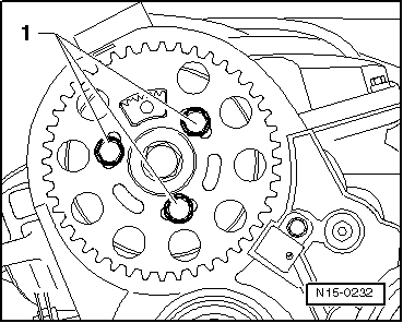
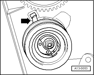
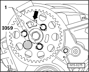
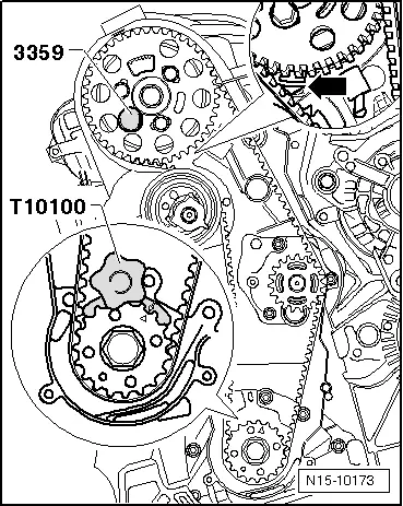
Turn crankshaft until marking on crankshaft pulley and tooth segment of camshaft pulley is on top. The marking on the rear toothed belt guard must align with the marking on the camshaft sender wheel -arrow-.
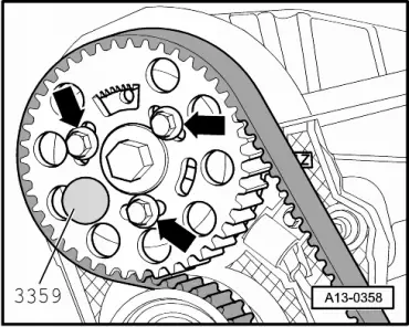
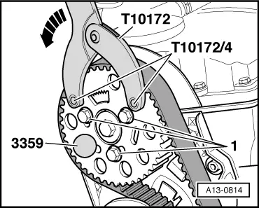
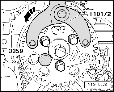
–  Lock hub using locking pin -3359-. To do this, slide locking pin through the free elongated hole on left into hole in cylinder head.
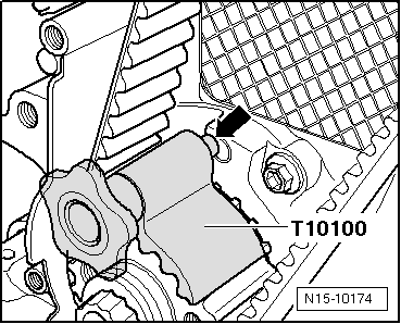
–  Lock crankshaft toothed belt pulley with crankshaft stop -T10100-. To do this, push crankshaft stop into teeth of belt pulley from face side.
  Note
The marks on the crankshaft toothed belt pulley and the crankshaft stop must align. When doing this, the pin of the crankshaft stop must engage in the drilling of sealing flange.
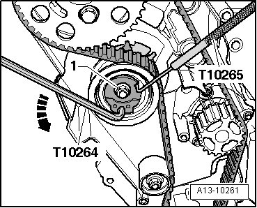
–  Mark direction of rotation of toothed belt.
  N15-10173
–  Loosen securing bolts -1- of camshaft pulley until the camshaft pulley can be moved within the elongated holes.
  N15-0232
–  Loosen tensioning roller securing nut -1-.
–  Turn eccentric of tensioning roller anti-clockwise -arrow- using socket -T10264-, until the tensioning roller can be locked with locking tool -T10265-.
  A13-10261
–  Now turn tensioning roller eccentric clockwise -arrow- onto stop and tighten securing nut -1- hand-tight.
–  Remove toothed belt first from coolant pump and then from remaining toothed belt pulleys.
Installing
l  Camshaft locked with locking pin -3359-.
l  Crankshaft locked with crankshaft stop -T10100-.
l  Tensioning roller locked with locking pin -T10265- and secured to right stop with securing nut.
  Note
Adjustment work on toothed belts must be performed only on cold engines, as the indicator position on the tensioning element varies depending on the engine temperature.
  A13-10262
–  Turn camshaft pulley in its elongated holes to centre position -arrows-.
–  Guide toothed belt through gap between engine support and engine.
–  Fit toothed belt onto crankshaft toothed belt pulley, tensioning roller, camshaft toothed belt pulley and idler roller.
–  Then fit toothed belt on coolant pump toothed belt pulley.
  Note
  A13-0358
Ensure that tensioning roller seats correctly in rear toothed belt guard -arrow-.
–  Remove locking pin -T10265- from tensioning roller.
–  Loosen tensioning roller securing nut -1-.
  A13-0053
–  Turn eccentric of tensioning roller clockwise -arrow- using special wrench, long reach -T10264- until indicator -2- is in middle of gap in base plate.
  Note
Ensure that securing nut does not turn as well.
–  Hold tensioning roller in this position and tighten tensioning roller nut to 20 Nm + turn 45° further.
  A13-10263
–  Fit counterhold -T10172- with pin -T10172/4- as shown in illustration, and keep the toothed belt under tension on pulling side, by pressing in -direction of arrow-.
–  Tighten bolts -1- of camshaft toothed belt pulley to 25 Nm.
–  Remove locking pin -3359- and crankshaft stop -T10100-.
–  Turn crankshaft two rotations in engine direction of rotation until the crankshaft is just before TDC again.
  A13-0814
–  Lock hub of camshaft with locking pin -3359- whilst turning engine in direction of rotation.
  A13-0358
–  Check whether crankshaft can be locked with crankshaft stop -T10100-.
If crankshaft cannot be locked:
  N15-10173
–  Loosen securing bolts -1- for camshaft toothed belt pulley.
  N15-0275
–  Turn crankshaft slightly against engine direction of rotation until the pin of the crankshaft stop is positioned just before the hole in the sealing flange -arrow-.
–  Now turn crankshaft in engine direction of rotation until crankshaft stop pin engages in sealing flange whilst turning.
  N15-10174
–  Fit counterhold -T10172- with pins -T10172/4- as shown. Press counterhold -T10172- in direction of arrow, keeping camshaft toothed belt pulley under tension.
–  In this position, tighten camshaft toothed belt pulley securing bolts -1- to 25 Nm.
–  Remove locking pin -3359- and crankshaft stop -T10100-.
–  Turn crankshaft two rotations in engine direction of rotation until crankshaft is just before TDC No. 1 cylinder.
–  Repeat check and adjustment if necessary.
–  Install centre and lower parts of toothed belt guard.
–  Install belt pulley vibration damper (renew securing bolts).
Tightening torque: 10 Nm + (90°) turn further
–  Install poly V-belt → Chapter.
–  Install upper toothed belt guard.
–  Install connecting pipe between charge air cooler and intake connecting pipe.
–  Install front right wheel housing liner.
–  Install coolant expansion tank.
  N15-10028
–  Bolt fuel filter bracket to engine mounting to 8 Nm torque -arrows-.
–  Engage fuel filter in bracket.
–  Bolt on filler neck for window wash system.
–  Fit engine cover.
  N10-10057

Removing and installing cylinder head > < Removing and installing toothed belt (vehicles with engine support bolted close to engine)