
Golf Mk5
| Changing and adjusting vacuum unit on turbocharger - only vehicles with engine code: BLS from model year 2008 |
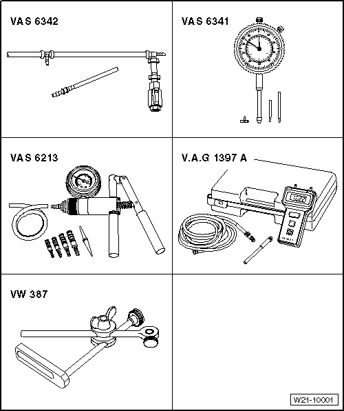
| Special tools and workshop equipment required |
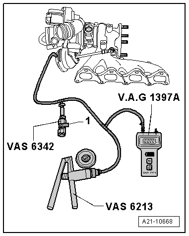
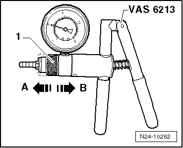
| t | Hand vacuum pump -VAS 6213- |
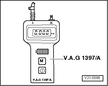
| t | Turbocharger tester -V.A.G 1397A- |
| t | Pressure regulating valve -VAS 6342- |
| t | Ring spanner -T10423- |
| t | Allen key, long reach -T10454- |
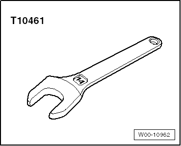
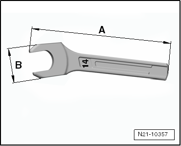
| t | 14 mm open-end spanner -T10461- |
 Note
Note
|
|
 Caution
|
|
|
|
|
|
|
|
|
|
|
|
|
|
|
|
Note
|
|
|
|
|
|
|
|
Note
|
|
|
|
|
|
Note |
|
|
|
Note
|
|
|
|
Note
|
|
Note
|
|
|
|
|
|
|
|
|
|