volkswagen Workshop Repair Guides

Volkswagen Workshop Service and Repair Manuals

Securing engine to assembly stand > < Removing and installing engine
Removing engine
   
Removing engine
Special tools and workshop equipment required
t  Lifting tackle -2024 A-
t  Engine bracket -T10012-
t  Support clamp -VW 313-
t  Engine and gearbox support -VW 540- or engine and gearbox support -VAS 6095-
t  Workshop crane -V.A.G 1202 A-
t  Drip tray -V.A.G 1306-

   
t  Torque wrench (5...50 Nm) -V.A.G 1331-
t  Torque wrench (40...200 Nm) -V.A.G 1332-
t  Engine and gearbox jack -V.A.G 1383 A-
t  Spring-type clip pliers -VAS 5024-
t  Ladder -VAS 5085-

Not illustrated:
t  
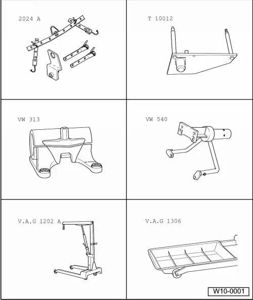
Container for removed parts -V.A.G 1698-
t  Engine bung set -VAS 6122-
t  Grease -G 000 100-
t  Cable ties
Procedure
  Note
t  Before carrying out further work, disconnect battery earth strap. First check whether a coded radio is fitted. Obtain radio code first if necessary.
t  The engine is removed downwards together with the gearbox.
t  Leave key in ignition to prevent steering wheel lock from engaging.
t  All cable ties which are opened or cut through when engine is removed must be replaced in the same position when engine is installed.
t  To prevent damage to removed components, place them in the container for removed parts -V.A.G 1698-.
t  Some components cannot be removed, or removed only with difficulty, with the engine installed. Therefore, you should determine all defective components before removing engine and renew them while engine is removed.
  WARNING
When doing any repair work, especially in the engine compartment, pay attention to the following due to the cramped conditions:
t  Route all the various lines (e.g. for fuel, hydraulics, activated charcoal filter system, coolant, refrigerant, brake fluid and vacuum) and electrical wiring in their original positions.
t  Ensure that there is sufficient clearance to all moving or hot components.
–  Read all fault memories before removal → Diagnostic tester VAS 5051; Guided fault finding; Vehicle system test or VAS 5052; Vehicle self-diagnosis.
–  With ignition switched off, disconnect earth strap from battery.
– 
–  Remove engine cover → Fig..
   
One-piece engine cover
For one-piece engine cover, pull engine cover abruptly upwards at front and right -arrows A-, then pull forwards out of rear fastening -arrow B-.
  N10-10000
Two-piece engine cover
For two-piece engine cover, first pull outer engine cover abruptly upwards at -arrows-, then pull inner engine cover abruptly upwards at -arrows-.
  N10-10221
–  Remove bolt -arrow- and pull air filter housing upwards out of mounting.
–  Remove air filter housing together with air mass meter and connecting pipe.
–  Remove battery and battery tray.
–  Remove plenum chamber bulkhead → General body repairs, exterior; Rep. Gr.50
  N10-10074
–  Pull off fuel supply hose -2-, fuel return hose -1- and coolant hose -3-.
  WARNING
t  The fuel and the fuel lines in the fuel system can become very hot (danger of scalding)!
t  The fuel system is also under pressure! Before opening the system, place cloths around the connections. Then carefully loosen connection to release the pressure!
t  Wear eye and hand protection when performing any type of repair work on the fuel system!
–  Remove sound insulation tray → General body repairs, exterior; Rep. Gr.50
–  Bring lock carrier into service position → General body repairs, exterior; Rep. Gr.50.
–  Drain coolant → Chapter.
Vehicles with air conditioner
  Note
To prevent damage to condenser and also to refrigerant lines/hoses, ensure that the lines and hoses are not stretched, kinked or bent.
To facilitate removing and installing engine without opening refrigerant circuit:
–  Remove poly V-belt → Chapter.
–  Remove air conditioner compressor from compact bracket → Heating, air conditioning; Rep. Gr.87.
–  Secure air conditioner compressor to lock carrier so that refrigerant lines are relieved.
Continuation for all vehicles
–  Unbolt left and right drive shafts from gearbox → Running gear, axles, steering; Rep. Gr.40.
  N10-10068
–  Unbolt pendulum support -arrows-.
–  Remove front exhaust pipe → Chapter.
–  Remove engine control unit → Chapter.
–  Release connector on engine control unit and pull off connector.
–  Remove leadthrough for engine control unit wiring harness.
  N10-0444
–  Open all cable guide fasteners -arrows-.
–  Remove wiring harness from cable guide on longitudinal member and lay to side on engine.
–  Pull off or disconnect all other electrical connections from engine and gearbox as necessary and lay to side.
–  Separate all connection, coolant, vacuum and intake hoses from engine.
–  Remove selector mechanism from gearbox: → 5-speed manual gearbox 0AH; Rep. Gr.34.
–  Separate pressure line for hydraulic clutch control.
–  Pull retainer for oil level and oil temperature sender -G266- off subframe.
  N10-10083
–  Insert engine support -T10012- in engine and gearbox jack -V.A.G 1383 A-.
  Note
Support pins must be secured to engine bracket -T10012- as shown. The threaded support pin must be on the gearbox side.
–  Fit engine bracket -T10012- to cylinder block with M10 x 25/ 8.8 bolt and tighten to approx. 40 Nm.
–  Raise engine and gearbox slightly using engine and gearbox jack -V.A.G 1383 A-.
  N10-0435
–  Unbolt assembly mounting on engine side from engine bracket -arrows-.
  Note
To remove securing bolts, use step ladder V.A.S -VAS 5085-.
  N10-0437
–  Unbolt assembly mounting on gearbox side from gearbox bracket -arrows-.
  Note
To remove securing bolts, use step ladder V.A.S -VAS 5085-.
–  Carefully lower engine with gearbox.
  Note
Engine with gearbox must be guided carefully when lowered to prevent damage to bodywork.
  N10-10082

Securing engine to assembly stand > < Removing and installing engine