
Golf Mk5
| Parts of cooling system - engine side |
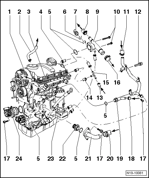
| 1 - | To top of expansion tank |
| q | Coolant hose schematic diagram → Chapter. |
| 2 - | From exhaust gas recirculation cooler to heat exchanger |
| q | Coolant hose schematic diagram → Chapter. |
| 3 - | Upper coolant pipe |
| q | Bolted to cylinder head cover. |
| q | Coolant hose schematic diagram → Chapter. |
| 4 - | To cylinder head |
| q | Coolant hose schematic diagram → Chapter. |
| 5 - | O-ring |
| q | Renew. |
| 6 - | Securing clip |
| q | Check for secure seating. |
| 7 - | Coolant temperature sender -G62- |
| 8 - | To exhaust gas recirculation cooler. |
| q | Coolant hose schematic diagram → Chapter. |
| 9 - | Connection |
| 10 - | 10 Nm |
| 11 - | From heat exchanger |
| q | Coolant hose schematic diagram → Chapter. |
| 12 - | 40 Nm |
| 13 - | From top of radiator |
| q | Coolant hose schematic diagram → Chapter. |
| 14 - | To upper coolant pipe |
| q | Coolant hose schematic diagram → Chapter. |
| 15 - | T-piece |
| 16 - | To top of radiator |
| q | Coolant hose schematic diagram → Chapter. |
| 17 - | 15 Nm |
| 18 - | From bottom of expansion tank |
| q | Coolant hose schematic diagram → Chapter. |
| 19 - | Coolant pipe |
| q | Coolant hose schematic diagram → Chapter. |
| 20 - | From bottom of radiator. |
| q | Coolant hose schematic diagram → Chapter. |
| 21 - | Connection |
| q | For thermostat. |
| 22 - | Thermostat |
| q | Removing and installing → Chapter. |
| q | Observe installation position → Chapter, Removing and installing thermostat. |
| q | Checking: Heat up thermostat in water. |
| q | Opening begins at approx. 85 °C. |
| q | Ends at approx. 105 °C. |
| q | Opening lift min. 7 mm. |
| 23 - | Oil cooler |
| q | Removing and installing → Chapter. |
| 24 - | Coolant pump |
| q | Check for ease of movement. |
| q | Note installation position. |
| q | Removing and installing → Chapter. |