volkswagen Workshop Repair Guides

Volkswagen Workshop Service and Repair Manuals

Assembly overview - intake manifold with intake manifold flap > < Removing
Installing
Installing
  Note
t  Each time work is performed which requires adjustment of the unit injector, the adjustment screw in the rocker arm and also the unit injector ball stud must be renewed.
t  New unit injectors are supplied with O-rings and heat shield seal.
–  Heat shield seal and O-rings must be renewed if old unit injector is reused → Chapter.
–  Check that the three O-rings and the heat shield seal along with securing clip are seated correctly before installing unit injector.
  Note
The seals must not be twisted.
–  Oil the seals and fit the unit injector into the cylinder head with great care.
–  Push the unit injector evenly into the cylinder head onto its limit stop.
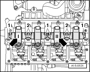
–  Fit the tensioning block into the slot on the side of the unit injector.
  Note
If the unit injector is not at right angles to the tensioning block the securing bolt may loosen and this can damage the unit injector or the cylinder head.
–  Therefore align the unit injector as follows.
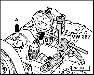
–  Screw the new securing bolt into the tensioning block until the unit injector can still be turned easily.
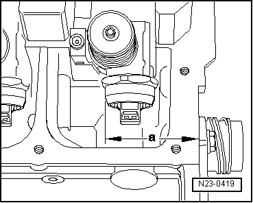
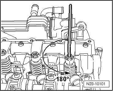
–  Now align unit injector at right angles to camshaft bearing pedestals.
   
–  Check dimension “a” from outer edge of cylinder head to rounded surface of unit injector with a vernier gauge (measuring range min. 400 mm).
  N23-0419
CylinderDimension “a”
1333.0 ± 0.8 mm
2245.0 ± 0.8 mm
3153.6 ± 0.8 mm
465.6 ± 0.8 mm

–  Align unit injector and tighten securing bolt as follows: 12 Nm and turn 270° (3/4 turn) further (turning further can be done in several stages).
   
–  Fit rocker arm shaft and tighten new securing bolts as follows:
–  First evenly tighten inner bolts -2- and then outer bolts -1- hand-tight. Then using same sequence, tighten to 20 Nm and 90° (1/4 turn) further evenly.
  A15-0531
–  Fit the dial gauge onto the adjustment screw of the unit injector as shown.
–  Turn the crankshaft in engine direction of rotation until the roller of the rocker arm is positioned on the peak of the drive cam. Roller side -arrow A- positioned at highest point dial gauge -arrow B- positioned at lowest point.
–  Remove dial gauge.
–  Now turn adjustment screw into rocker arm until a firm resistance is felt (unit injector positioned at stop).
  N23-0337
–  Turn adjustment screw back off stop by 180°.
–  Hold adjustment screw in this position and tighten the lock nut to 30 Nm.
–  Connect unit injector connector.
–  Install cylinder head cover → Chapter.
–  Install toothed belt guard.
  N23-10101

Assembly overview - intake manifold with intake manifold flap > < Removing