volkswagen Workshop Repair Guides

Volkswagen Workshop Service and Repair Manuals

Securing engine to assembly stand > < Removing engine
Procedures for Golf, Golf Plus, Touran
–  Read fault memories of all control units before removal → Diagnosis tester VAS 5051; Guided fault finding; Vehicle system test or VAS 5052; Vehicle self-diagnosis.
–  With ignition switched off, disconnect earth strap from battery. → Electrical system; Rep. gr.27.
   
–  Remove engine cover.
To do this, pull engine cover upwards abruptly at front and right -arrows A- and then pull forwards out of rear fastening -arrow B-.
–  Remove plenum chamber bulkhead. → General body repairs, exterior; Rep. gr.50.
  N10-0451
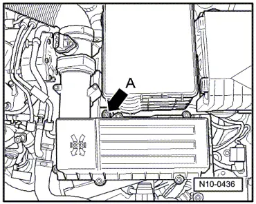
–  Remove air filter housing with air mass meter and connecting pipe.
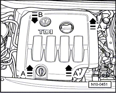
Remove bolt -arrow A- and pull air filter housing upwards out of mounting.
–  Remove battery and battery tray.
–  Remove insulation tray → General body repairs, exterior; Rep. gr.50.
–  Bring lock carrier into service position → General body repairs; Rep. gr.50.
–  Drain coolant → Chapter
  WARNING
t  The fuel and the fuel lines in the fuel system can become very hot (danger of scalding)!
t  The fuel system is also under pressure! Before opening the system, place cloths around the connections. Then carefully loosen connection to release the pressure!
t  Wear eye and hand protection when performing any type of repair work on the fuel system!
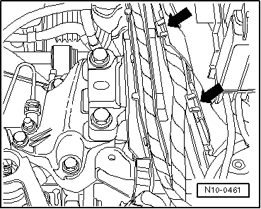
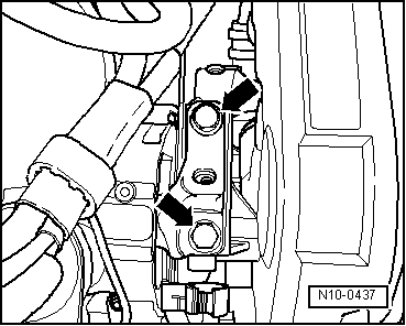
–  Disconnect fuel supply and return lines as well as coolant line on cylinder head.
–  Pull fuel filter module upwards out of bracket and lay it with hoses to side.
Vehicles with air conditioner
  Note
To prevent damage to condenser and also to refrigerant lines/hoses, ensure that the lines and hoses are not stretched, kinked or bent.
To facilitate removing and installing engine without opening refrigerant circuit:
–  Remove poly V-belt → Chapter.
–  Separate air conditioner compressor from compact bracket. → Heating, air conditioning; Rep. gr.87.
–  Secure air conditioner compressor to lock carrier so that refrigerant lines are relieved.
Continuation for all vehicles
–  Remove exhaust pipe and coolant hoses from supplementary heater.
–  Remove connecting pipes between charge air cooler and engine.
–  Pull retainer for wiring harness of oil level and oil temperature sender -G266- off subframe.
–  Remove right drive shaft and unscrew left drive shaft from gearbox → Running gear, axles, steering; Rep. gr.40.
–  Remove left wheel housing liner.
–  Disconnect front exhaust pipe from turbocharger, loosen double clamp and slide exhaust pipe back → Chapter.
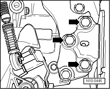
–  Pull engine wiring harness connector off control unit:
   Golf → Chapter
   Golf Plus, Touran → Chapter
  N10-0436
–  Open cable guide catches on longitudinal member -arrows-.
–  Remove wiring harness from cable guide and lay to side on engine.
  N10-0461
For engine code BMN:
–  Separate connections at engine bulkhead for:
t  -1-Exhaust gas temperature sender 2 -G448-
t  -2-Temperature sender after particulate filter -G527-
t  -3-Exhaust gas temperature sender 1 -G235-
t  -4-Lambda probe -G39-
t  -5-Charge pressure control solenoid valve -N75-
Continuation for all vehicles
–  Pull off or disconnect all other electrical connections from engine and gearbox as necessary and lay to side.
–  Separate all connecting, coolant, vacuum and intake hoses from engine.
For engine code BMN:
–  Release connecting clamp for front exhaust pipe/front silencer.
–  Remove subframe and steering → Running gear, axles, steering; Rep. gr.40.
  Note
The engine is lowered downwards with particulate filter fitted.
Engine codes AZV, BKD:
–  Disconnect front exhaust pipe from turbocharger, loosen double clamp and slide exhaust pipe back → Chapter.
Continuation for all vehicles:
–  Disconnect selector mechanism from gearbox → 6-speed manual gearbox 02Q; Rep. gr.34.
–  Separate pressure line for hydraulic clutch control.
–  Remove pendulum support.
  N10-10208
–  Insert engine bracket -T10012- in engine and gearbox jack -V.A.G 1383/A-.
  Note
Support pins must be secured to engine bracket -T10012- as shown. The threaded support pin must be on the gearbox side.
–  Fit engine bracket -T10012- to cylinder block with M10 x 25/ 8.8 bolt and tighten to approx. 40 Nm.
–  Lift engine and gearbox lightly using engine and gearbox jack -V.A.G 1383/A-.
  N10-0435
–  Unbolt engine side of assembly mounting from engine support from above -arrows-.
  N10-0437
–  Unbolt gearbox side of assembly mounting from gearbox bracket from above -arrows-.
  Note
t  To remove securing bolts, use stepladder VAS 5085.
t  Engine with gearbox must be guided carefully when lowered to prevent damage to bodywork.
–  Carefully lower engine with gearbox.
  N10-0445

Securing engine to assembly stand > < Removing engine