| –
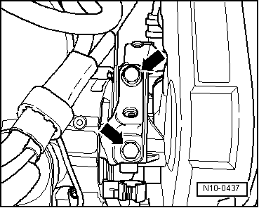
| Bolt engine assembly mounting to engine support -arrows- by bringing contact surfaces together using support bracket -10-222A-. Specified torque: 60 Nm + 90° (1/4 turn) further |
| Further assembly is basically the reverse of the dismantling sequence. In the process, note the following: |
| t
| Ensure that fuel hose connections are tight. |
| t
| Do not interchange supply and return lines (return line blue or with blue markings, supply line black). |
| t
| When installing charge air pipes, ensure that locking lugs engage correctly. |
| –
| Install wheel housing liner. |
|
|
|
 Note
Note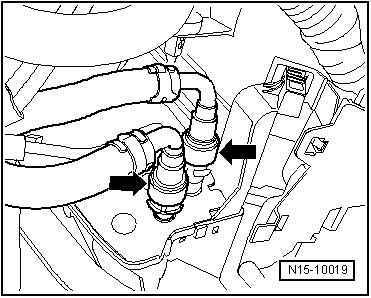
 WARNING
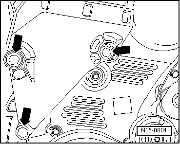
 Caution