volkswagen Workshop Repair Guides

Volkswagen Workshop Service and Repair Manuals

Cleaning unit injectors (engine codes BMN, BKP, BMA, BUZ and BMR) > < Assembly overview - unit injector
Removing and installing unit injector
   
Removing and installing unit injector
Special tools and workshop equipment required
t  Universal dial gauge bracket -VW 387-
t  Special wrench, long reach -3410-
t  Special wrench, long reach -T10054-
t  Torque wrench -V.A.G 1331/-
t  Slide hammer -T10133/3-
t  Puller -T10163-

   
t  Assembly tool -2036-
  W00-10141
t  Valve lever -VW 541/1 A- with press tool -VW 541/5-
  W00-0248
t  Torque wrench -V.A.G 1783-
Removing
–  Remove upper toothed belt guard and cylinder head cover.
–  Remove pre-wiring for unit injectors → Chapter and place it to side. The central connector of the pre-wiring may remain in the cylinder head.
  W00-0990
–  Loosen lock nut of adjustment screw -A- and back out screw until respective rocker arm lies against plunger spring of unit injector.
–  Remove rocker arm securing bolts -5…1- (from outwards to inwards) using socket -3410- and remove rocker arm shaft.
–  Loosen securing bolts -B- for unit injectors using special wrench -T10054- and remove bolts.
–  Pull ball stud out of injector unit.
  N23-10001
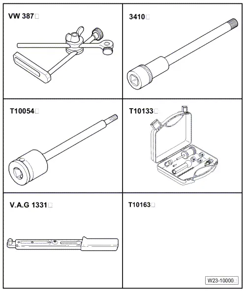
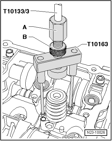
–  Insert puller -T10163- in bolt holes on unit injector.
–  Turn spindle -A- down lightly onto the unit injector. Hand-tighten lock nut -B-.
–  Pull unit injector upwards out of cylinder head seat with cautious taps of slide hammer -T10133/3-.
Do not interchange unit injectors which have been used.
Installing
  Caution
Each time work is performed which requires adjustment of the unit injector via adjustment screw, the adjustment screw in the rocker arm and also the unit injector ball stud must be renewed, otherwise excessive wear of the components is the result.
. It is absolutely necessary to renew the securing bolts of the unit injector.
–  Before installing unit injector, check that new seals are properly seated.
  Note
t  New unit injectors are supplied with O-rings.
t  If old unit injector is reused, O-rings must be renewed → Chapter.
t  The seals must not be twisted.
–  Oil the seals and stem of unit injector.
–  Check seat of unit injector in cylinder head for soiling or foreign objects (metal shavings/carbon deposits etc.) and clean with compressed air, if necessary.
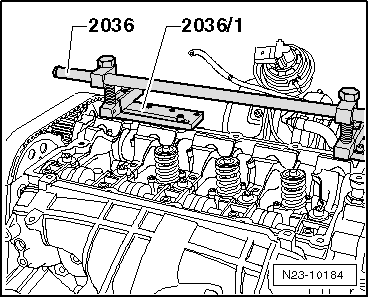
–  Insert unit injector into cylinder head with great care.
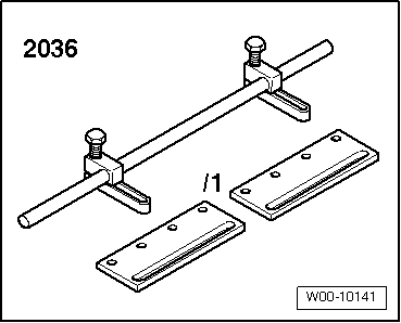
  Note
If the securing plates -2036/1- cannot be fitted as described below, due to the exhaust gas recirculation cooler, use other tools to raise the item, e.g. large washers.
  N23-10026
–  Fit valve assembly device -2036- with securing plates -2036/1- on retaining frame of cylinder head as shown.
  Caution
If the unit injector is pulled down by the securing bolts, there is a risk of the unit injector not being pulled correctly into its seat. This can result in engine running problems and starting problems. For this reason the unit injector may only be secured after it has been pushed in its seat.
  N23-10184
–  Fit the new securing bolts and carefully screw in by hand onto stop -arrow- without force.
  N23-10185
–  Now fit valve lever -VW 541/1 A- with thrust piece -VW 541/5-.
–  Carefully press unit injector in its seat using valve lever -VW 541/1 A- and maintain this force.
–  Carefully screw in securing bolts of unit injector by hand and without force onto stop using special wrench, long reach -T10054-.
–  Tighten new securing bolts as follows:
Stage I = 3 Nm
Stage II = 1/4 turn (90°) further
Stage III = 1/2 turn (180°) further
  Note
Renew adjustment bolts -A- and ball pins of unit injector.
  N23-10186
–  Put rocker arm shaft in place and evenly tighten new securing bolts in the sequence 1…5 hand tight.
–  Then evenly tighten to 20 Nm and 90° (1/4 turn) further in the same sequence.
  N23-10001
–  Fit dial gauge onto adjustment screw of unit injector as shown.
–  Turn the crankshaft in engine direction of rotation until the roller of the rocker arm is positioned on the peak of the drive cam. Roller side -arrow A- positioned at highest point. Dial gauge -arrow B- positioned at lowest point.
–  Remove dial gauge.
–  Now turn adjustment screw into rocker arm until a firm resistance is felt (unit injector positioned at stop).
  N23-10024
–  Turn adjustment screw 180° back off stop.
–  Hold adjuster screw in this position and tighten lock nut to 30 Nm.
–  Push on unit injector connector and install cylinder head cover and toothed belt guard.
  N23-10101

Cleaning unit injectors (engine codes BMN, BKP, BMA, BUZ and BMR) > < Assembly overview - unit injector