
Golf Mk5
| Coolant hose schematic diagram |
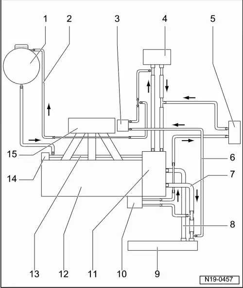
| 1 - | Expansion tank |
| 2 - | Coolant hose |
| q | from exhaust gas recirculation valve -N18- with exhaust gas recirculation potentiometer -G212- |
| 3 - | Exhaust gas recirculation valve -N18- with exhaust gas recirculation potentiometer -G212- |
| 4 - | Heat exchanger for heater unit |
| 5 - | Gearbox oil cooler |
| q | Only for automatic gearbox. |
| 6 - | Coolant hose |
| q | to Exhaust gas recirculation valve -N18- with exhaust gas recirculation potentiometer -G212- |
| 7 - | Upper coolant hose |
| 8 - | Lower coolant hose |
| 9 - | Radiator |
| 10 - | Engine oil cooler |
| q | Only engine codes BAG, BLP, BLF |
| 11 - | Thermostat housing |
| 12 - | Cylinder head/cylinder block |
| 13 - | Coolant pipe |
| 14 - | Coolant pump |
| 15 - | Intake manifold |