volkswagen Workshop Repair Guides

Volkswagen Workshop Service and Repair Manuals

Removing and installing camshaft housing > < Removing and installing timing chain and chain drive for oil pump (engine codes BAG, BLP, BLF)
Removing and installing timing chain and chain drive for oil pump (engine codes BKG, BLN)
   
Removing and installing timing chain and chain drive for oil pump (engine codes BKG, BLN)
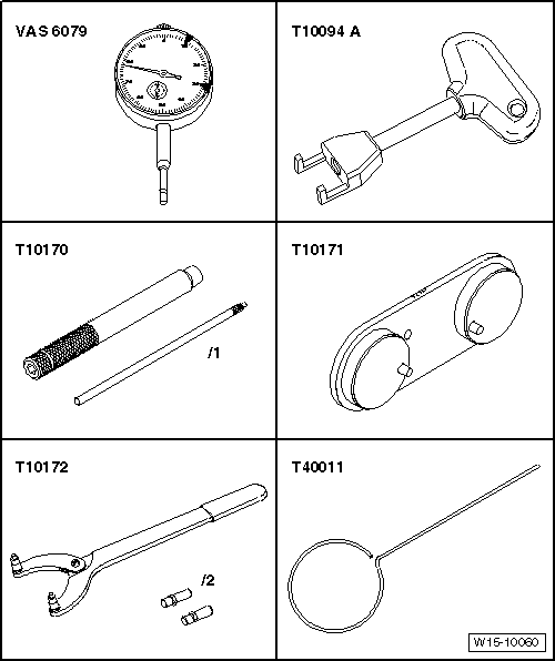
Special tools and workshop equipment required
t  Dial gauge -VAS 6079-
t  Puller -T10094 A-
t  Dial gauge adapter -T10170-
t  Camshaft clamp -T10171-
t  Counterhold tool -T10172-
t  Locking pin -T40011-

   
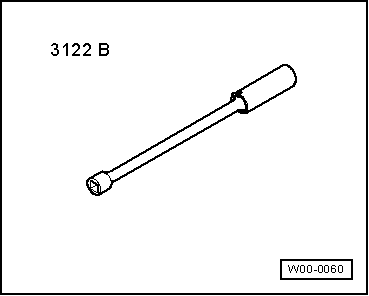
t  Spark plug socket and extension -3122 B-
  W00-0060
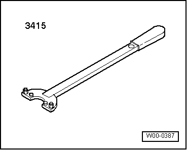
t  Counterhold tool -3415-
t  Torque wrench (5…50 Nm) -V.A.G 1331-
Removing
–  Remove air filter → Chapter.
–  Remove exhaust gas recirculation valve -N18- and unscrew camshaft sealing cover → Chapter.
–  Remove spark plug from No. 1 cylinder. To do this, use puller -T10094 A- and spark plug wrench -3122 B-.
  W00-0387
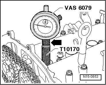
–  Screw dial gauge adapter -T10170- into spark plug hole to stop.
–  Screw dial gauge -VAS 6079- and extension -T10170/1- in to stop and lock in position with lock nut -arrow-.
–  Turn crankshaft in direction of engine rotation, to TDC No. 1 cylinder. Note position of small needle on dial gauge.
  N15-0653
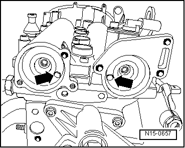
The holes -arrows- in the camshaft must align as shown. Otherwise turn crankshaft one rotation (360°) further.
  Note
t  If crankshaft is turned more than 0.01 mm past TDC, then turn crankshaft back 45° against engine direction of rotation. Then turn crankshaft in direction of engine rotation to TDC No. 1 cylinder.
t  Permissible deviation from TDC No. 1 cylinder: ± 0.01 mm.
  N15-0657
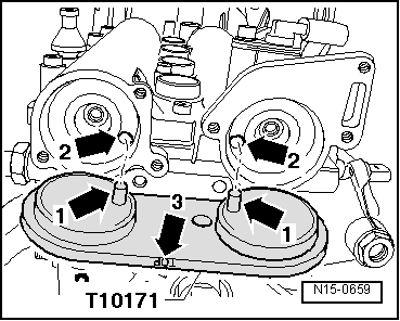
–  Insert camshaft clamp -T10171- to stop in camshaft openings.
Locking pins -arrows 1- must engage in holes -arrows 2-. Inscription „TOP“-arrow 3- must be readable from above.
  N15-0659
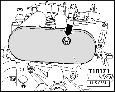
–  Install a M6 bolt -arrow- hand-tight (do not tighten) to secure camshaft clamp -T10171-.
–  Remove valve timing housing → Chapter.
  N15-0661
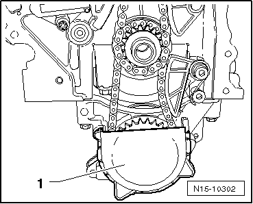
–  Pull cover -1- off chain sprocket for oil pump.
  N15-10302
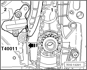
–  Press tensioning rail in -direction of arrow- by hand and lock piston of chain tensioner with locking pin -T40011-.
  N15-10301
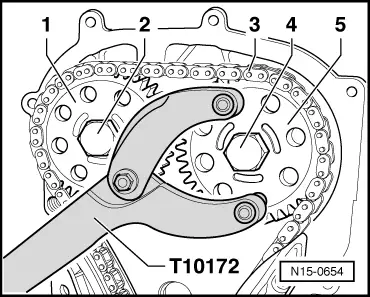
–  Mark direction of rotation of timing chain -3- using coloured felt tip marker pen.
–  Unscrew bolts -2- and -4- and remove chain sprocket -1- together with timing chain -3-. Counterhold using counterhold -T10172-.
  N15-0654
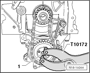
–  Hold oil pump chain sprocket with counterhold -T10172- and loosen securing bolt -1-.
  N15-10300
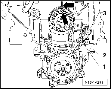
–  Use a screwdriver on bolt -2- to release tensioning spring -1- then remove tensioning spring -1-.
–  Unscrew securing bolt -3- and remove chain tensioner.
–  Mark direction of rotation of oil pump drive chain -2- using felt-tip marker.
  N15-10299
–  Remove securing bolt for chain sprocket -1- and remove chain sprockets -1- and -3- together with drive chain for oil pump -2-.
Installing
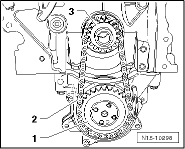
l  The crankshaft must be positioned at TDC No. 1 cylinder.
  N15-10298
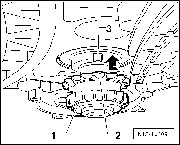
–  Push chain sprocket -1- in -direction of arrow- onto crankshaft journal as far as the stop.
  Caution
Cast lug -2- on chain sprocket -1- must seat in groove -3- on crankshaft journal.
  N15-10309
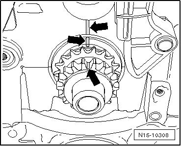
–  Mark position of chain sprocket and crankshaft to cylinder block using a felt-tip marker.
  N15-10308
–  Place oil pump drive chain -3- onto drive chain sprocket -1- and position drive chain sprocket -2- onto oil pump drive shaft at same time.
  Note
t  Note running direction mark on oil pump drive chain.
t  Oil pump drive sprocket only fits on oil pump drive shaft in one position -arrow-.
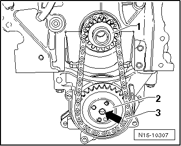
  N15-10307
–  Hold oil pump drive sprocket with counterhold -T10172-.
–  Tighten securing bolt -1- to 20 Nm + 90° further.
  N15-10300
–  Position chain tensioner on oil pump drive chain and tighten securing bolt -3- to 15 Nm.
–  Lever tensioning spring -1- onto bolt -2- using a screwdriver.
  Note
t  Note marks -arrows-.
t  The crankshaft must not rotate.
–  Tighten chain sprocket -3- hand-tight with new securing bolt.
  Note
The illustration shows the timing chain with camshaft adjuster. The procedure of work is as follows:
  N15-10299
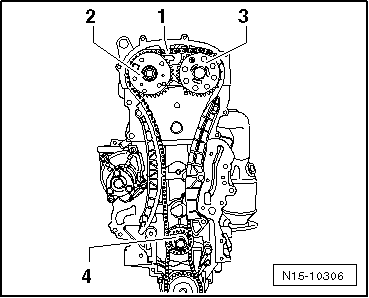
–  Place timing chain -1- on crankshaft chain sprocket -4- and exhaust camshaft chain sprocket -3- and tighten inlet camshaft chain sprocket -2- hand-tight using a new bolt.
  Note
Note running direction mark on timing chain -1-.
  N15-10306
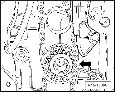
Timing chain must lie on guide rail -1- and crankshaft chain sprocket -arrow-.
  N15-10305
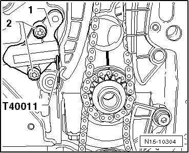
–  Install chain tensioner -1- and tighten securing bolts -2- to 9 Nm.
–  Tension timing chain by pulling locking pin -T40011- from chain tensioner.
–  Check marks on crankshaft chain sprocket and cylinder block; they must align.
  N15-10304
–  Hold camshaft sprockets -1- and -5- in this position with counterhold -T10172- then tighten bolts -2- and bolt -4- to 50 Nm.
  Note
Securing bolts -2- and -4- are only tightened 90° further once timing has been checked.
  N15-0654
–  Unscrew bolt -arrow- and remove camshaft clamp -T10171- from camshaft housing.
–  Check valve timing → Chapter
If valve timing is OK:
  N15-0661
–  Hold camshaft chain sprockets with counterhold -T10172- and tighten bolts -2- and -4- 90° further with a rigid wrench.
  Note
Camshaft sprockets must not move on camshaft whilst tightening.
  N15-0654
–  Install oil pump wheel cover -1-.
–  Install timing housing → Chapter.
Further assembly is basically the reverse of the dismantling sequence.
  N15-10302

Removing and installing camshaft housing > < Removing and installing timing chain and chain drive for oil pump (engine codes BAG, BLP, BLF)