volkswagen Workshop Repair Guides

Volkswagen Workshop Service and Repair Manuals

Specified torques > < Securing engine to assembly stand
Installing engine
Installing engine
Installation is carried out in the reverse order. When installing, note the following:
  Caution
When doing any repair work, especially in the engine compartment, pay attention to the following due to the cramped conditions:
t  
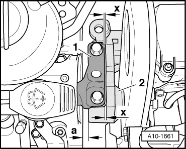
Route all the various lines (e.g. for fuel, hydraulics, activated charcoal filter system, coolant and refrigerant, brake fluid and vacuum) and electrical wiring in their original positions.
t  To avoid damage to lines, ensure sufficient clearance to all moving or hot components.
–  Check clutch release bearing for wear and renew if necessary.
–  Lightly grease clutch release bearing, release bearing guide sleeve and splines on input shaft with G 000 100.
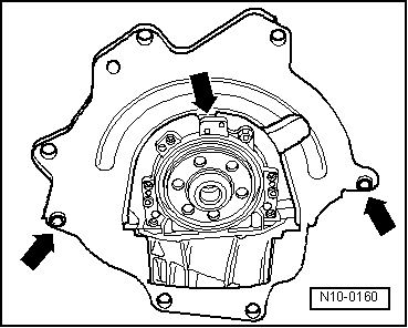
–  Check whether dowel sleeves for centring engine/gearbox have been fitted in cylinder block, insert if necessary.
   
–  Hook intermediate plate onto sealing flange and slide onto dowel sleeves -arrows-.
–  When swinging engine in, ensure that there is clearance between drive shafts.
Align engine mountings as follows:
  N10-0160
t  There must be a distance -a- of at least 10 mm between engine support and longitudinal member (right side).
t  The side surface of the engine support -2- should be located parallel to the support arm -1-.
  A10-1661
t  Ensure that edges of support arm on gearbox assembly mounting -2- and gearbox support -1- are parallel on gearbox side.
–  Install pendulum support.
  Note
Specified torques for assembly mountings → Chapter.
–  Install drive shafts → Running gear, axles, steering; Rep. gr.40.
–  Install air conditioner compressor → Heating, air conditioning system; Rep. gr.87.
–  Install poly V-belt → Chapter.
–  Electrical connections and routing: → Electrical system; Rep. gr.97.
–  Install hydraulic clutch slave cylinder: → 6-speed manual gearbox 02S; Rep. gr.30.
–  Attach selector mechanism: → 6-speed manual gearbox 02S; Rep. gr.34.
–  Install engine splash protection.
–  Replenish coolant → Chapter.
–  Install air filter → Chapter.
–  Install battery and battery tray → Electrical system; Rep. gr.27.
–  Connect battery → Electrical system; Rep. gr.27.
Engine cover ► November 2006
  A10-1662
–  Place vacuum hose -2- onto vacuum reservoir union -1-.
  Note
Ensure that the vacuum hose is locked onto the union -2-.
  N15-10326
–  Push engine cover panel down at points -1- in direction of -arrow- until it engages.
Engine cover November 2006 ►
  N10-10172
–  Push engine cover panel down at points -1- in direction of -arrow- until it engages.
–  Fit vacuum hose onto connection -arrow-.
–  Connect Vehicle diagnosis tester.
–  Erase learnt values and adapt engine control unit to regulating value control unit and throttle valve module → Vehicle diagnostic tester„Guided functions“.
–  Carry out vehicle system test → Vehicle diagnostic tester„Guided fault finding“.
–  Finish the vehicle system test so that any fault entries stored during assembly can be deleted automatically.
Observe applicable safety precautions during road test.
–  Carry out a road test.
–  Then carry out vehicle system test again and rectify any faults which may have occurred.
  N10-10222

Specified torques > < Securing engine to assembly stand