volkswagen Workshop Repair Guides

Volkswagen Workshop Service and Repair Manuals

Securing engine to assembly stand > < Removing and installing engine (Golf, Golf Plus, Touran)
Removing engine
Removing engine
  Note
t  Crankcases were installed with different size threaded holes.
t  Check these holes before dismantling/assembling and install the respective engine support.
t  The engine support -T40075- can continue to be used if converted as described in the respective work sequence.
t  The fitting of engine support -T40075- and engine support -T40075A- on the crankcase is described in the respective work sequence.
Converting engine support -T40075-
   
–  Scribe dimensions -a- and -b- as shown.
Dimension -a-: 24.5 mm
Dimension -b-: 49.0 mm
–  Mark position with a centre punch.
–  Drill a hole with a 13.0 mm bit.
–  Identify engine support with an -A- behind tool designation.
  N10-10236
Special tools and workshop equipment required
t  Engine support -T40075- with adapters /4, /5, /6 or engine support -T40075A- (not illustrated) with adapters /4, /5, /6
t  Torque wrench (5…50 Nm) -V.A.G 1331-
t  Engine and gearbox jack -V.A.G 1383 A-
t  Engine and gearbox support -VAS 6095-
t  Drip tray for workshop hoist -VAS 6208-

   
t  Spring-type clip pliers -VAS 5024A-
t  Stepladder -VAS 5085-
t  Torque wrench (40…200 Nm) -V.A.G. 1332-
t  Guide rods -T10093-

  Note
Before carrying out further work, disconnect battery earth strap. Check whether a coded radio is fitted. Obtain anti-theft coding first if necessary.
Engine cover ► November 2006
   
–  Release vacuum hose on vacuum reservoir -arrow- and pull it off.
–  Lift engine cover panel at points -1- and pull it forwards in direction of -arrow-.
Engine cover November 2006 ►
  N10-10172
–  Pull vacuum hose off -arrow-.
–  Lift engine cover panel at points -1- and pull it forwards in direction of -arrow-.
  N10-10222
–  Unbolt heat shield over turbocharger -arrows-.
–  Remove air filter → Chapter.
–  Open and close expansion tank cap to release pressure in cooling system.
–  Drain coolant → Chapter.
  Note
Pull coolant hoses off engine with spring-type clip pliers -VAS 5024A-.
–  Release hose guides -arrows- and remove coolant hose -1- from coolant reservoir.
  N21-10064
–  Remove hose -2- from activated charcoal filter system solenoid valve 1 -N80- to activated charcoal filter.
  N10-10176
–  Separate fuel supply line -1- and line to activated charcoal filter -2-. Press release tabs to do this.
–  Seal lines so that fuel system is not contaminated by dirt.
–  Observe rules for cleanliness → Chapter.
  N10-10177
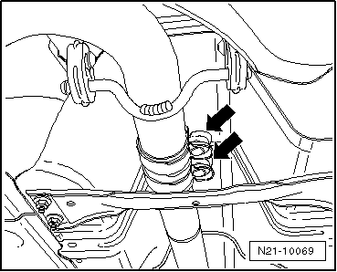
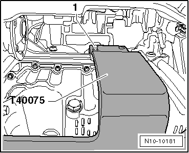
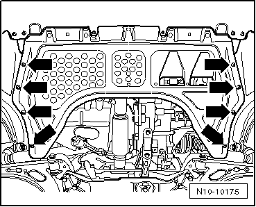
–  Remove securing bolts -arrows- of engine splash protection.
–  Remove front left and right wheel housing liners → General body repairs; Rep. gr.66.
–  Bring lock carrier into service position → General body repairs, exterior; Rep. gr.50.
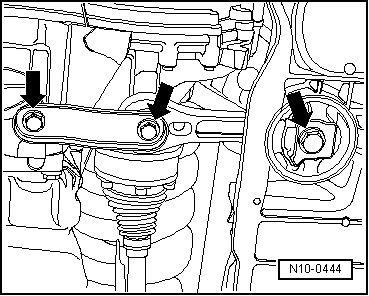
The engine is removed downwards together with the gearbox.
–  Disconnect battery → Electrical system; Rep. gr.27.
–  Remove battery and battery holder → Electrical system; Rep. gr.27.
–  All cable ties which are opened or cut through when engine is removed must be replaced in the same position when engine is installed.
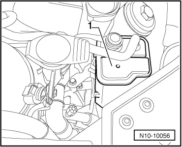
–  Disconnect all electrical wiring from gearbox, alternator and starter and lay to side.
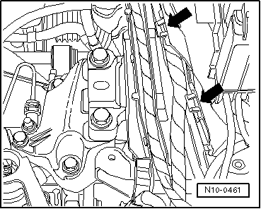
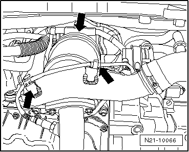
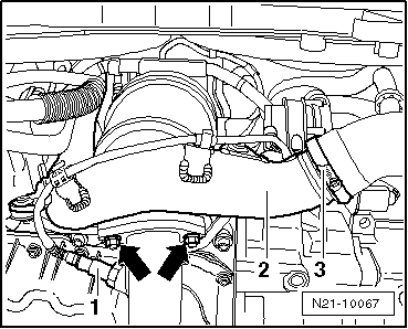
–  Pull off or disconnect all other electrical connections as necessary from engine and lay to side.
  WARNING
Fuel supply lines are under pressure! Wear eye protection and gloves to avoid injuries and skin contact. Before loosening hose connections, wrap a cloth around the connection. Then release pressure by carefully pulling hose off connection.
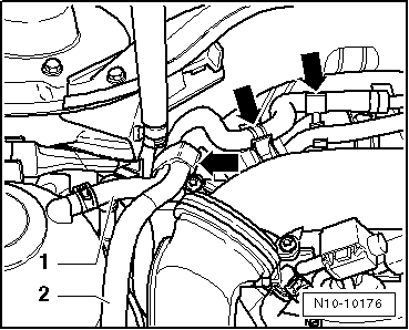
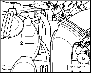
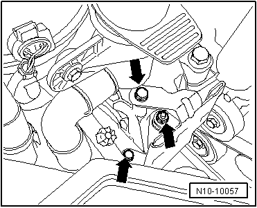
–  Pull vacuum and breather hoses off engine.
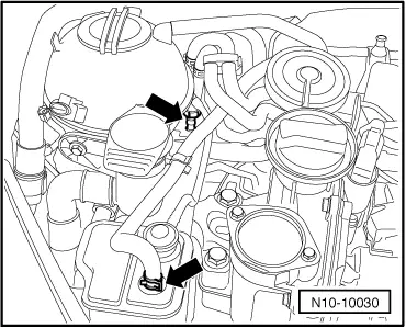
–  Pull connectors off thermal switch and radiator fan.
–  Remove plenum chamber bulkhead → General body repairs; Rep. gr.50.
–  Removing and installing anti-theft engine control unit (Golf) → Chapter.
–  Removing and installing anti-theft engine control unit (Golf Plus, Touran) → Chapter.
  N10-10175
–  Open all line guide fasteners -arrows-.
–  Remove wiring from engine control unit.
–  Secure lines/wiring to engine with a cable tie.
Golf, Golf Plus only
  N10-0461
–  Remove hoses for activated charcoal filter -arrows-.
  N10-10030
–  Pull activated charcoal filter -1- upwards out of bracket.
  N10-10056
–  Unbolt bracket -arrows-.
Continuation for all vehicles
–  Remove wiring for Lambda probe after catalytic converter -G130- and for alternator from cable guides -arrows-.
  N10-10057
–  Pull connector off Lambda probe after catalytic converter -G130- and remove.
  N21-10066
–  Open hose clip -3- and remove charge air pipe -2-.
–  Unbolt exhaust pipe from catalytic converter -arrows-.
  N21-10067
–  Unbolt exhaust pipe together with flexible joint -arrows-.
  N21-10068
–  Loosen securing bolts of double clamp -arrows- and pull exhaust pipe to rear.
  N21-10069
–  Disconnect pendulum support -arrows-.
–  Unbolt selector mechanism from gearbox → 6-speed manual gearbox 02S; Rep. gr.34.
–  Remove strut -1-.
  N10-0444
–  Remove slave cylinder -arrows- and lay to side. Do not open hydraulic system.
–  Remove hydraulic clutch slave cylinder: → 6-speed manual gearbox 02S; Rep. gr.30
  Note
Clutch pedal must not be depressed.
–  Remove poly V-belt → Chapter.
–  Remove air conditioner compressor → Heating, air conditioning system; Rep. gr.87.
  Note
The air conditioning system lines must not be opened.
–  Secure air conditioner compressor to lock carrier.
–  Ensure that lines are not kinked.
–  Observe additional information and installation work → Chapter.
–  Remove right drive shaft, and unscrew left drive shaft from gearbox and tie up: → Running gear, axles, steering; Rep. gr.40.
–  Bring lock carrier into service position → General body repairs, exterior; Rep. gr.50.
Work sequence with engine support -T40075-
  A10-1630
Engine support -T40075- with adapters -/4-, -/5- and -/6- is required to to lower engine with gearbox.
  N10-10180
–  Screw adapter T40075/4 into crankcase to stop.
–  Position the engine support -T40075- with adapters -/5- and -/6- on crankcase.
  N10-10182
–  Secure engine support -T40075- hand-tight to crankcase using bolt -1-.
  N10-10181
–  Tighten all bolts on engine support -T40075- to 20 Nm.
–  Lift engine and gearbox lightly using engine and gearbox jack -V.A.G 1383 A-.
Work sequence with engine support -T40075A-
  N10-10179
Engine support -T40075A- with adapters -/4-, -/5- and -/6- is required to to lower engine with gearbox.
  N10-10234
–  Screw adapter T40075A /4 into the crankcase to stop.
–  Position the engine support -T40075A- with adapters -/5- and -/6- on crankcase.
  N10-10248
–  Secure engine support -T40075A- hand-tight to crankcase using bolt -1-.
  N10-10235
–  Tighten all bolts on engine support -T40075A- to 20 Nm.
  N10-10249
–  Unbolt engine side of assembly mounting from above -arrows-.
  N10-0443
–  Unbolt gearbox side of assembly mounting from above -arrows-.
  Note
t  To remove securing bolts use a stepladder -VAS 5085-.
t  When lifted out, the assembly must be carefully guided to prevent damage to the bodywork.
–  Carefully lower engine and gearbox.
  N10-10183

Securing engine to assembly stand > < Removing and installing engine (Golf, Golf Plus, Touran)