volkswagen Workshop Repair Guides

Volkswagen Workshop Service and Repair Manuals

Checking cooling system for leaks > < Coolant hose schematic diagram (engine codes BLG, BMY)
Draining and filling coolant
   
Draining and filling coolant
Special tools and workshop equipment required
t  Refractometer -T10007-
t  Hose clip pliers -VAS 6340-
t  Cooling system charge unit -VAS 6096-

Draining
  WARNING
Steam may escape when expansion tank is opened. Wear eye protection and protective clothing to avoid eye injuries and scalding. Cover cap with cloth and open carefully.
–  Open filler cap on coolant expansion tank.
–  Remove engine splash protection.
Engine codes BLG, BMY
   
–  Pull off retaining clip -arrow- and remove coolant hose from radiator.
Engine code BWK
  N19-0276
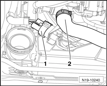
–  Detach spring-type clip and pull off coolant hose -2-.
Disregard item -1-.
  Note
Observe environmental regulations for disposal.
Filling
  Note
The amount of water used in the coolant mixture has a great influence on its effectiveness. Because the water quality differs from country to country and even region to region, Volkswagen has decided to define the quality of the water to be used in the coolant system. Distilled water fulfils all requirements. It is therefore recommended that distilled water be mixed with the coolant when it is topped up or completely replaced. This also applies to older models. For new models (model year 2010 ▶) the use of distilled water is compulsory.
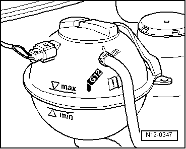
  Caution
Only distilled water may be mixed with G12 plus-plus. The use of distilled water ensures optimum protection against corrosion.
  Note
t  In vehicles as of model year 2008, only G 12 plus-plus according to TL VW 774 G may be used as coolant additive.
t  For vehicles up to and including model year 2007 coolant additive G 12 plus according to TL VW 774 F and G 12 plus-plus according to TL VW 774 G can be used.
t  It is only permissible to use distilled water for mixing.
t  The coolant additive G 12 plus-plus can be mixed with the previous coolant additive G 12 plus. Identification: both are coloured purple.
t  Coolant additives marked conforming to „TL VW 774 G“ or conforming to „TL VW 774 F“ prevent frost and corrosion damage, scaling and also raise boiling point of coolant. Therefore, the cooling system must be filled all year round with frost and corrosion protection additives.
t  Because of its higher boiling point, the coolant improves engine reliability under heavy loads, particularly in countries with tropical climates.
t  Frost protection is required down to about -25°C (in countries with arctic climates: down to about -35°C).
t  The coolant concentration must not be reduced by adding distilled water even in the warm season or in hot countries. The coolant additive concentration must be at least 40%.
t  If for climatic reasons greater frost protection is required, the amount of coolant additive can be increased, but only up to 60 % (frost protection to about -40 °C). Otherwise frost protection and cooling effectiveness are reduced again.
t  If radiator, heat exchanger, cylinder head or cylinder head gasket is renewed, do not reuse old coolant.
Recommended mixing ratios (use only distilled water for mixing):
  N19-10240
Frost protection
to
Amount of anti-freeze
Coolant additive → RemarkDistilled water → Remark
-25 °C
-35 °C
40 %
50 %
2.25 l
2.8 l
3.35 l
2.8 l

1)  The quantity of coolant can vary depending upon vehicle equipment.
   
–  Press connection against radiator and slide retaining clip -arrow- into groove.
–  Install engine splash protection.
With cooling system charge unit -VAS 6096-
–  Fill coolant circuit using cooling system charge unit -VAS 6096- → Operating instructions for cooling system charge unit VAS 6096.
Without cooling system charge unit -VAS 6096-
  N19-0276
–  Fill with coolant up to max. mark on expansion tank.
With or without cooling system charge unit -VAS 6096-
–  Fit expansion tank cap.
–  Turn off heater controls.
Vehicles with no auxiliary heater
–  Start engine and maintain an engine speed of about 2,000 rpm for about 3 minutes.
–  Run engine until radiator fan -V7- cuts in.
Vehicles with auxiliary heater
  Caution
Do not switch auxiliary heater on until the cooling circuit has been filled as subsequently described.
  N19-0347
–  Connect vehicle diagnosis tester as follows:
–  Push diagnosis cable connector onto diagnosis connection in driver footwell.
–  Start engine and maintain an engine speed of about 2,000 rpm for about 3 minutes.
–  Press buttons on display for „Vehicle self-diagnosis“, „18 - Auxiliary heater“ and „03 - Final control diagnosis“ one after the other.
–  Press right arrow button on display up to final control diagnosis for heater coolant shut-off valve -N279-.
–  Initiate final control diagnosis for heater coolant shut-off valve -N279-. Continue to maintain engine speed of approx. 2,000 rpm for about 1 minute.
–  Run engine until radiator fan -V7- cuts in.
Continuation for all vehicles
  WARNING
Steam may escape when expansion tank is opened. Wear eye protection and protective clothing to avoid eye injuries and scalding. Cover cap with cloth and open carefully.
–  Check coolant level and top up if necessary. When the engine is at normal operating temperature, the coolant level must be on the max. mark; when the engine is cold, between the min. and max. marks.
  N01-0590

Checking cooling system for leaks > < Coolant hose schematic diagram (engine codes BLG, BMY)