volkswagen Workshop Repair Guides

Volkswagen Workshop Service and Repair Manuals

Securing engine to assembly stand > < Removing engine
Procedure
Procedure
–  Disconnect earth strap at battery with ignition switched off → Electrical system; Rep. Gr.27
   
–  Remove engine cover.
  A10-1564
–  Unscrew bolt -3- and remove air filter housing with connecting hoses.
–  Remove battery and battery tray.
–  Remove plenum chamber bulkhead → General body repairs, exterior; Rep. Gr.50
–  Pull engine wiring harness connector off control unit.
  A10-1570
–  Release retainer for engine wiring harness -arrow- and pull off upwards.
  A10-1574
–  Open cable guide catches on longitudinal member -arrows-.
–  Separate connectors between engine wiring harness and body. Lay engine wiring harness on engine.
  WARNING
The fuel supply line is under pressure! Wear eye protection and protective clothing to avoid injuries and skin contact. Before loosening hose connections, wrap a cloth around the connection. Then release pressure by carefully pulling hose off connection.
  N10-0461
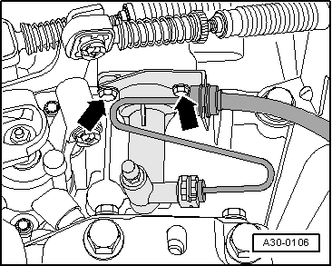
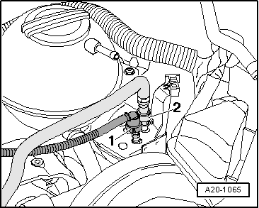
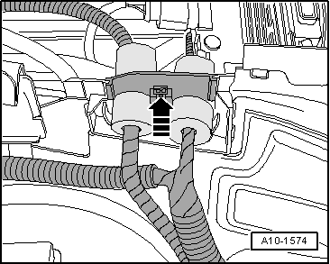
–  Disconnect breather line -1- and fuel supply line -2- by pressing release buttons.
–  Remove noise insulation → General body repairs, exterior; Rep. Gr.50.
–  Bring lock carrier into service position → General body repairs; Rep. Gr.50.
–  Drain coolant → Chapter.
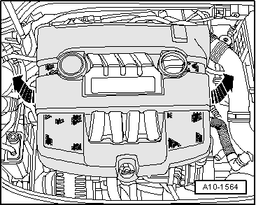
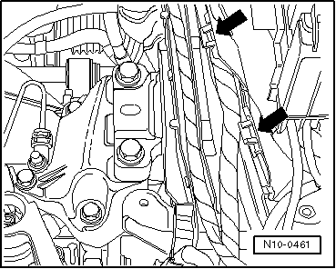
–  Pull off or disconnect all other electrical lines from engine and gearbox as necessary and lay to side.
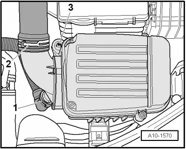
–  Separate all connection, coolant, vacuum and intake hoses from engine.
Vehicles with air conditioning
  Note
To prevent damage to condenser and to refrigerant lines, ensure that lines are not stretched, kinked or bent.
Removing engine without opening refrigerant circuit:
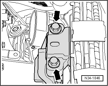
–  Remove poly V-belt → Chapter.
–  Remove air conditioner compressor from ancillary bracket → Heating, air conditioning; Rep. Gr.87.
–  Secure air conditioner compressor to lock carrier so that the refrigerant lines are not under tension.
Vehicles with manual gearbox:
–  Remove selector mechanism from gearbox → 5-speed manual gearbox 0AF; Rep. Gr.34.
  A20-1065
–  Remove slave cylinder -arrows- and lay to side. Do not open hydraulic system.
  Note
Do not press clutch pedal after removing slave cylinder.
Vehicles with an automatic gearbox:
–  Disconnect selector lever cable from gearbox → Automatic gearbox 09G; Rep. Gr.37.
Continuation for all vehicles:
–  Remove front exhaust pipe together with catalytic converter → Chapter.
–  Remove pendulum support.
–  Remove right drive shaft and unbolt left drive shaft at gearbox → Running gear, axles, steering; Rep. Gr.40.
  A30-0106
–  Remove grub screw -arrow- from front of cylinder block.
–  Insert engine bracket -T10012- in engine and gearbox jack -V.A.G 1383 A-.
  A10-1639
–  Position engine bracket -T10012- on cylinder block as shown and bolt on with M10 x 25 bolt to approx. 20 Nm.
–  Lift engine and gearbox lightly using engine and gearbox jack -V.A.G 1383 A-.
  N10-0056
–  Unbolt engine side of assembly mounting from engine bracket from above -arrows-.
  N10-0437
–  Unbolt gearbox side of assembly mounting from gearbox bracket -arrows- from above.
  Note
t  To remove securing bolts, use stepladder -VAS 5085-.
t  Engine with gearbox must be guided carefully when lowering to prevent damage to bodywork.
–  Carefully lower engine with gearbox.
  N34-1846

Securing engine to assembly stand > < Removing engine