
Golf Mk5
| Coolant hose schematic diagram |
 Note
Note| Inclusion of auxiliary heater in coolant circuit → Rep. gr.82 |
| Vehicles with manual gearbox |
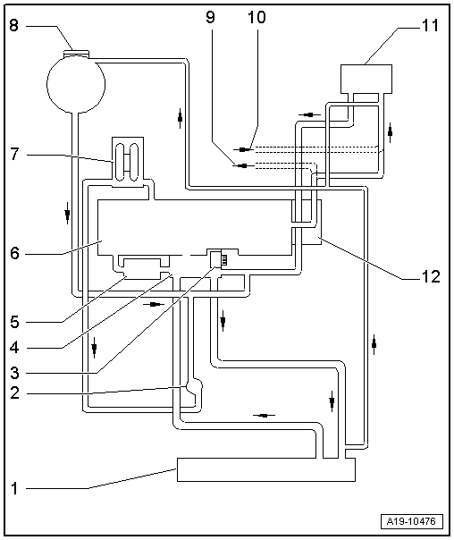
| 1 - | Radiator |
| 2 - | Continued coolant circulation pump -V51- |
| 3 - | Coolant pump |
| 4 - | Thermostat |
| 5 - | Engine oil cooler |
| 6 - | Cylinder head and cylinder block |
| 7 - | Turbocharger |
| 8 - | Coolant expansion tank |
| q | With cap |
| q | Checking pressure relief valve in filler cap → Chapter. |
| 9 - | To auxiliary heater |
| 10 - | From auxiliary heater |
| 11 - | Heat exchanger for heater unit |
| 12 - | Coolant connection |
| Vehicles with automatic gearbox |
Note| Inclusion of auxiliary heater in coolant circuit → Rep. gr.82 |

| 1 - | Radiator |
| 2 - | Continued coolant circulation pump -V51- |
| 3 - | Thermostat |
| 4 - | Coolant pump |
| 5 - | Engine oil cooler |
| 6 - | Cylinder head and cylinder block |
| 7 - | Turbocharger |
| 8 - | Coolant expansion tank |
| q | With cap |
| q | Checking pressure relief valve in filler cap → Chapter. |
| 9 - | To auxiliary heater |
| 10 - | From auxiliary heater |
| 11 - | Heat exchanger for heater unit |
| 12 - | Gearbox oil cooler |
| 13 - | Coolant connection |
| 14 - | Thermostat for gear oil cooler |
| q | In some vehicles, the thermostat is located on the output side of the gear oil cooler |