
Golf Mk5
| Assembly overview - pistons and conrods |
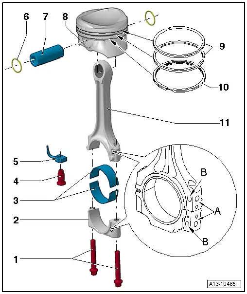
| 1 - | Conrod bolt |
| q | M8: 30 Nm + turn 90° further. |
| q | M9: 45 Nm + turn 90° further. |
| q | Renew. |
| q | Oil threads and contact surface. |
| q | Use old bolt for measuring radial clearance. |
| q | For radial clearance measurement, do not turn 90° further |
| 2 - | Conrod bearing cap |
| q | Note installation position. |
| q | The caps only fit in one position and only on the appropriate conrod due to the breaking procedure (cracking) separating the cap from the conrod. |
| q | Mark with cylinder number -A-. |
| q | Installation position: Marking -B- faces towards pulley end. |
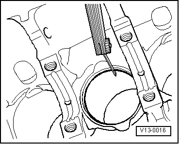
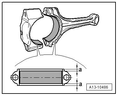
| 3 - | Bearing shells |
| q | Installation position → Fig.. |
| q | Do not interchange used bearing shells (mark). |
| q | Axial clearance new: 0.10…0.35 mm , wear limit: 0.40 mm |
| q | Measure radial clearance using Plastigage; new: 0.02…0.06 mm; wear limit: 0.09 mm. Do not rotate crankshaft when checking radial clearance. |
| 4 - | Pressure relief valve |
| q | 27 Nm |
| q | Opening pressure: 1.6…1.9 bar |
| 5 - | Oil spray jet |
| q | For piston cooling. |
| 6 - | Circlip |
| 7 - | Piston pin |
| q | If difficult to remove, heat piston to approx. 60 °C. |
| q | Remove and install using drift -VW 222 A-. |
| 8 - | Piston |
| q | Check → Anchor. |
| q | Mark installation position and cylinder number. |
| q | Arrow on piston crown points to belt pulley end. |
| q | Install using piston ring clamp. |
| q | Piston and cylinder dimensions → Chapter. |
| q | Checking cylinder bores → Anchor. |
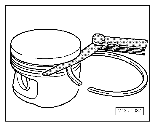
| 9 - | Compression rings |
| q | Offset gaps by 120°. |
| q | Use piston ring pliers to remove and install. |
| q | „TOP“ must face towards piston crown |
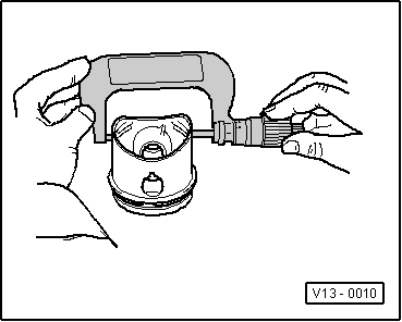
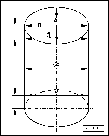
| q | Checking ring gap → Fig.. |
| q | Checking ring-to-groove clearance → Fig.. |
| 10 - | Oil scraper ring |
| q | 2 parts |
| q | Offset gap of top steel element of piston ring by 120° to next compression ring |
| q | Offset gaps of individual parts of oil scraper ring. |
| q | Checking ring gap → Fig.. |
| q | Ring-to-groove clearance cannot be checked. |
| 11 - | Conrod |
| q | Renew as set only. |
| q | Mark with cylinder number -A-. |
| q | Installation position: Marking -B- faces towards pulley end. |
|
|
| Piston ring dimensions in mm | New | Wear limit |
| compression ring | 0.20 … 0.40 | 0.8 |
| Oil scraper ring | 0.25 … 0.50 | 0.8 |
|
|
| Piston ring dimensions in mm | New | Wear limit |
| 1st compression ring | 0.06 … 0.09 | 0.20 |
| 2nd compression ring | 0.03 … 0.06 | 0.15 |
| Oil scraper rings | Not measurable | |
|
|
|
 Caution
 Note
Note
|
|
|
|