
Golf Mk5
|
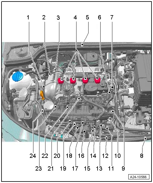
| 1 - | Inlet camshaft control valve 1 -N205- |
| q | Removing and installing → Chapter |
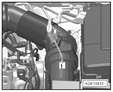
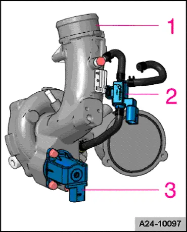
| 2 - | Charge pressure control solenoid valve -N75- |
| q | Installed directly on turbocharger → Fig.. |
| 3 - | Turbocharger air recirculation valve -N249- |
| q | Installed directly on turbocharger → Fig.. |
| 4 - | Ignition coils with output stages |
| q | Removing and installing → Chapter |
| q | Ignition coil 1 with output stage -N70- |
| q | Ignition coil 2 with output stage -N127- |
| q | Ignition coil 3 with output stage -N291- |
| q | Ignition coil 4 with output stage -N292- |
| q | Puller -T40039- is required for removing ignition coils from cylinder head. |
| 5 - | Engine control unit -J623- |
| q | Removing and installing - Passat, CC → Chapter. |
| q | Removing and installing - Golf, Eos → Chapter |
| q | Removing and installing - Tiguan → Chapter |
| q | Removing and installing - Scirocco → Chapter |
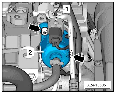
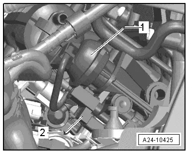
| 6 - | High-pressure pump with fuel pressure regulating valve -N276- |
| q | Location: |
| Engine codes BZB, CAWA, CAWB, CBFA, CCTA, CCTB, CGYA, CDAA, CDAB → Fig.. |
| Engine codes CCZA, CCZB, CCZC, CCZD → Fig. |
| q | Removing and installing → Chapter |
| q | Assembly overview - high pressure pump → Chapter. |
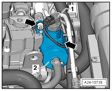
| 7 - | Fuel pressure regulating valve -N276- |
| q | Location: |
| Engine codes BZB, CAWA, CAWB, CBFA, CCTA, CCTB, CGYA, CDAA, CDAB → Fig.. |
| Engine codes CCZA, CCZB, CCZC, CCZD → Fig. |
| 8 - | Radiator outlet coolant temperature sender -G83- |
| q | Passat, CC, Golf, Eos, Scirocco: In lower union on radiator → Chapter. |
| q | Tiguan: in coolant hose → Chapter |
| 9 - | Vacuum unit for air flow control flaps |
| q | Fitting location → Fig. |
| 10 - | Intake manifold flap air flow control valve -N316- |
| q | Fitting location → Fig. |
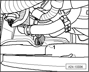
| 11 - | Engine speed sender -G28- |
| q | Location: Bottom left at front → Fig.. |
| 12 - | Charge air pressure sender -G31- |
| q | Fitting location → Fig. |
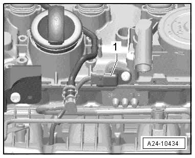
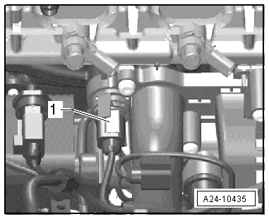
| 13 - | Electrical connector for knock sensor 1 -G61- |
| q | Location: Below intake manifold → Fig.. |
| q | Knock sensor 1 -G61- tightening torque: 20 Nm |
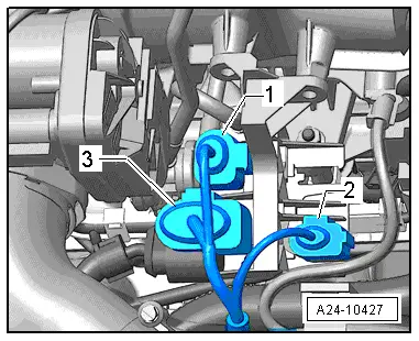
| 14 - | Electrical connector for Hall sender -G40- |
| q | Location: Below intake manifold → Fig.. |
| 15 - | 8-pin connector for injectors |
| q | Location: Below intake manifold → Fig.. |
| 16 - | Throttle valve module -J338- |
| q | Including throttle valve drive (electric throttle operation) -G186-, angle sender 1 for throttle valve drive (electric throttle operation) -G187- and angle sender 2 for throttle valve drive (electric throttle operation) -G188-. |
| q | After renewing throttle valve module -J338- it must be reprogrammed to engine control unit -J623- → Vehicle diagnostic tester. |
| 17 - | Activated charcoal filter solenoid valve 1 -N80- |
| 18 - | Intake air temperature sender -G42- |
| q | Bolted to front intake manifold → Chapter. |
| 19 - | Knock sensor 1 -G61- |
| q | Location: Below intake manifold. |
| q | Specified torque: 20 Nm |
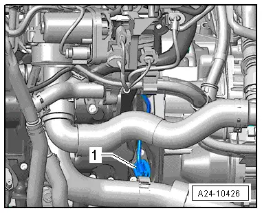
| 20 - | Coolant temperature sender -G62- |
| q | In coolant pump housing → Fig.. |
| 21 - | Hall sender -G40- |
| q | Bolted to front cylinder head cover → Fig.. |
| 22 - | Fuel pressure sender -G247- |
| q | On fuel rail → Chapter. |
| 23 - | Intake manifold flap potentiometer -G336- |
| q | On intake manifold on right |
| q | To remove and install, remove intake manifold → Chapter. |
| 24 - | Oil pressure switch -F1- |
| q | In bracket for ancillary units. |
| Engine codes CAWA, CAWB, CBFA, CCTA, CCTB, BZB, CGYA → Chapter. |
| Engine codes CCZA, CCZB, CCZC, CCZD, CDAA, CDAB → Chapter |
| A - | Diagnostic connector |
| q | In driver's footwell. |
| B - | Air mass meter -G70- and intake air temperature sender 2 -G299- |
| q | Fitting location → Fig. |
| q | Removing and installing → Chapter |
| C - | Accelerator position sender -G79- and accelerator position sender 2 -G185- |
| q | On accelerator (both senders are accommodated in one housing) |
| q | If accelerator module or engine control unit is renewed, kick-down function must be taught-in on vehicles with automatic gearbox. |
| q | Removing and installing → Chapter |
| D - | Radiator fan control unit -J293- |
| q | The radiator fan control unit -J293- is integrated into the radiator fan -V7-. |
| E - | Injectors |
| q | In fuel rail |
| q | Removing and installing → Chapter |
| q | Injector, cylinder 1 -N30- |
| q | Injector, cylinder 2 -N31- |
| q | Injector, cylinder 3 -N32- |
| q | Injector, cylinder 4 -N33- |
|
|
|
|
|
|
|
|
|
|
|
|
|
|
 Note
Note
|
|
|
|
|
|
|
|