volkswagen Workshop Repair Guides

Volkswagen Workshop Service and Repair Manuals

Pre-tensioning chain tensioner > < Removing oil pump with balancer shaft gear assembly
Removing and installing oil pump with balancer shaft gear assembly
l  Chain tensioner preloaded → Chapter
Engine codes AXW, BLX, BLY, BLR:
  Note
t  The intermediate plate must always be renewed.
t  Observe expiry date of sealing compound.
t  The balancer shaft gear assembly with intermediate plate and sump must be installed and bolts tightened immediately after the silicone sealant has been applied.
–  Remove sealant residue on cylinder block with a flat scraper.
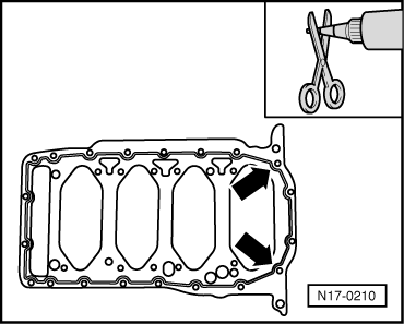
–  Cut off tube nozzle at forward marking (approx. 3 mm nozzle Ø).
   
–  Apply silicone sealant onto clean sealing surface of new intermediate plate as illustrated.
Observe the following points:
t  The sealant bead must be 2…3 mm thick.
t  The bead of sealant must pass round the inside of the bolt holes as shown in the illustration -arrows-.
t  The sealant must face the cylinder block. No sealant is required on the sump side.
  Note
The sealant bead must not be thicker, otherwise excess sealant will enter the oil sump and may block the oil suction line strainer.
  N17-0210
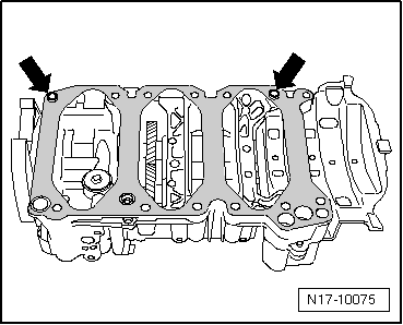
–  Place intermediate plate over dowel sleeves of balancer shaft gear assembly as shown -arrows-.
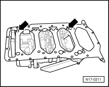
Engine codes BVX, BVY, BVZ:
  N17-0211
–  Place intermediate plate over dowel sleeves of balancer shaft gear assembly as shown -arrows-.
Continuation for all vehicles:
  N17-10075
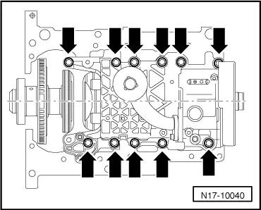
–  Install oil pump with balancer shaft gear assembly and intermediate plate. Tighten securing bolts from inside outwards to 15 Nm + 1/4 turn (90°) further.
  Note
Note different bolt lengths → Fig.
  N17-10040
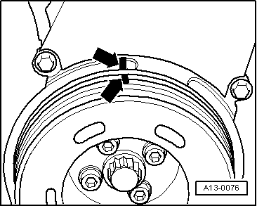
–  Turn crankshaft to TDC No. 1 cylinder.
  A13-0076
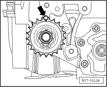
–  Align marking on balancer wheel shaft chain sprocket -arrow- with locking hole.
  N17-10238
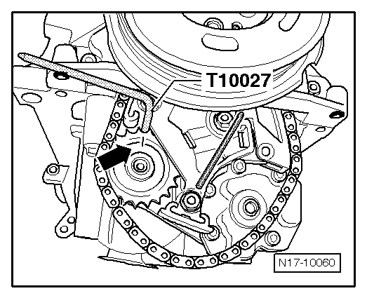
–  Lock sprocket in this position using locking pin -T10027-. Place chain on chain sprocket of balancer shaft.
–  Install oil pump chain sprocket and hand-tighten the bolt.
  Note
The oil pump chain sprocket can only be installed correctly in one position. For installation, only the oil pump may be turned.
  N17-10060
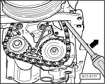
–  Remove locking pin -T10027- and hexagon socket key -1-. Secure oil pump chain sprocket. Specified torque: 20 Nm + 1/4 turn (90°) further. Counterhold on centre bolt of vibration damper.
–  Installing sump:
   Engine codes AXW, BLX, BLY, BLR → Chapter.
   Engine codes BVX, BVY, BVZ → Chapter
Further assembly is basically the reverse of the dismantling procedure.
  N17-0177
Bolt allocation for balancer shaft gear assembly
A - Hexagon head collar bolt M7x40
B - Hexagon head collar bolt M7x55
C - Hexagon head collar bolt M7x90
D - Hexagon head flange bolt M7x115
E - Plug with O-ring
  N17-10041

Pre-tensioning chain tensioner > < Removing oil pump with balancer shaft gear assembly