
Golf Mk5
| Assembly overview - pistons and conrods |
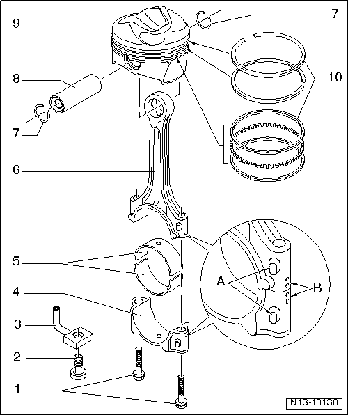
| 1 - | Conrod bolt, 30 Nm + 1/4 turn (90°) further |
| q | Renew |
| q | Oil threads and contact surface. |
| q | To measure radial clearance, tighten to 30 Nm but not further. |
| 2 - | Pressure relief valve, 27 Nm |
| q | Opening pressure: 1.3...1.6 bar |
| 3 - | Oil spray jet |
| q | For piston cooling. |
| 4 - | Conrod bearing cap |
| q | Note installation position. |
| q | Due to the cracking method used to separate the bearing cap from the conrod in manufacture, the caps only fit in one position and only on the appropriate conrod. |
| q | Mark cylinder number -B- |
| q | Installation position: markings -A- face towards pulley end. |
| 5 - | Bearing shell |
| q | Note installation position → Chapter |
| q | Do not interchange used bearing shells. |
| q | Axial clearance new: 0.10…0.35 mm, wear limit 0.4 mm |
| q | Measure radial clearance using Plastigage; new: 0.02…0.06 mm; wear limit: 0.09 mm. Do not rotate crankshaft when checking radial clearance. |
| 6 - | Conrod |
| q | With industrially cracked conrod cap. |
| q | Only renew as a complete set. |
| q | Mark cylinder number -B- |
| q | Installation position: markings -A- face towards pulley end. |
| 7 - | Circlip |
| 8 - | Piston pin |
| q | If difficult to remove, heat piston to 60 °C. |
| q | Remove and install with drift -VW 222 A-. |
| 9 - | Piston |
| q | Checking → Fig. |
| q | Mark installation position and cylinder number. |
| q | Arrow on piston crown points to belt pulley end. |
| q | Install using piston ring clamp. |
| q | Checking cylinder bores → Fig.. |
| q | Piston and cylinder dimensions → Chapter. |
| 10 - | Piston rings |
| q | Offset gaps by 120° |
| q | Remove and install using piston ring pliers. |
| q | Markings to piston crown |
| q | Checking ring gap → Fig.. |
| q | Checking ring-to-groove clearance → Fig.. |