
Golf Mk5
| Coolant hose schematic diagram (vehicles from 06.2005) |
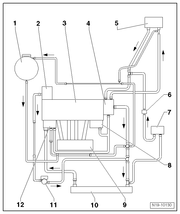
| 1 - | Expansion tank |
| q | With cap |
| q | Checking pressure relief valve in filler cap → Chapter. |
| 2 - | Turbocharger |
| q | Removing and installing → Chapter. |
| 3 - | Cylinder head/cylinder block |
| q | If renewed, refill system with fresh coolant. |
| 4 - | Coolant connection |
| 5 - | Heat exchanger for heater |
| q | If renewed, refill system with fresh coolant. |
| 6 - | Bypass thermostat |
| q | Only for automatic gearbox. |
| q | Check → Chapter. |
| 7 - | Gearbox oil cooler |
| q | Only for automatic gearbox. |
| 8 - | Engine oil cooler |
| 9 - | Intake manifold |
| q | Removing and installing → Chapter. |
| 10 - | Radiator |
| q | Removing and installing → Chapter. |
| q | If renewed, refill system with fresh coolant. |
| 11 - | Coolant circulation pump -V50- |
| q | The flow of the coolant in the run-on phase is opposite to the flow shown. |
| q | The function can be checked using final control diagnosis → Vehicle diagnostic tester |
| 12 - | Thermostat housing |
| q | With thermostat. |
| q | Checking thermostat → Vehicle diagnostic tester„Function and component selection“. |