volkswagen Workshop Repair Guides

Volkswagen Workshop Service and Repair Manuals

Removing and installing intake manifold flap motorV157 and intake manifold flap potentiometerG336 > < Assembly overview - intake manifold
Removing and installing intake manifold
Removing:
  WARNING
Observe safety precautions when releasing fuel pressure in high-pressure section → Chapter
  Note
t  Observe rules for cleanliness → Chapter.
t  If an injector was pulled out of the cylinder head when the intake manifold was removed, the Teflon seal must be renewed → Chapter.
t  Assembly overview - intake manifold → Chapter.
–  Remove throttle valve module -J338- → Chapter.
–  Disconnect all electrical connectors as necessary.
–  Disconnect vacuum hose between intake manifold and vacuum pump at intake manifold.
  WARNING
The fuel system is pressurised!
t  Wear eye protection and protective clothing to avoid possible injury and skin contact.
t  Before loosening line connections, wrap a cloth around the connection. Then release pressure by carefully pulling off line.
   
Engine code BPY:
–  Disconnect lines -1, 2 and 3-. Do this by operating release buttons.
  A10-1623
Engine codes AXX, BWA
–  Disconnect fuel supply line -2-.
  A20-1065
–  Disconnect breather line -2-.
Continuation for all vehicles:
  N10-10185
Pull vacuum lines -arrows- off intake manifold and cylinder head cover.
  WARNING
The fuel system is pressurised!
t  Wear eye protection and protective clothing to avoid possible injury and skin contact.
t  Before loosening line connections, wrap a cloth around the connection. Then release pressure by carefully pulling off line.
  N24-10188
Vehicles up to 05.2006:
–  Unscrew fuel pipe -4- from connection -3-. At the same time counterhold connection -3-.
–  Unscrew banjo bolt -2-, at the same time counterhold connection -1-.
  N24-10576
Vehicles from 05.2006:
–  Open hose clip -1- and pull fuel hose off.
–  Unscrew fuel pipe -3-, at the same time counterhold connection -2-.
Continuation for all vehicles:
  N24-10577
–  Disconnect coolant pipe and oil dipstick tube from intake manifold -arrows- and remove oil dipstick tube from engine by pulling it upwards.
  N24-10136
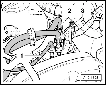
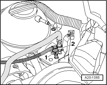
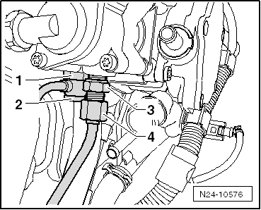
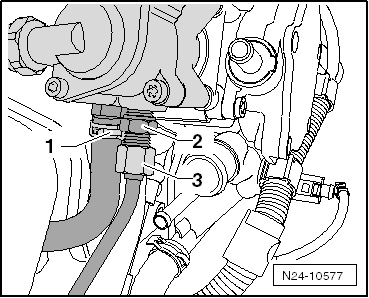
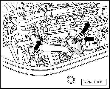
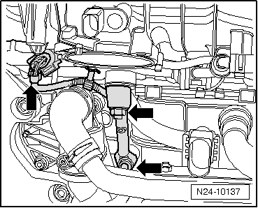
–  Remove intake manifold support -arrows- and disconnect connector -1- from fuel pressure sender -G247-.
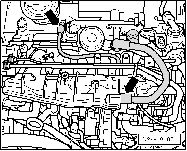
–  Unscrew all bolts from intake manifold.
–  Carefully pull intake manifold and fuel rail off cylinder head.
Installing:
Installation is carried out in the reverse order. When installing, note the following:
If an injector was pulled out of the cylinder head when the intake manifold was removed, renew the Teflon seal of the injector → Chapter.
Renew O-rings between injector and fuel rail and moisten slightly with clean engine oil.
Fit intake manifold with fuel rail on cylinder head and evenly press onto injectors.
If the intake manifold flap motor -V157- or the intake manifold were renewed, the intake manifold flap potentiometer -G336- must be adapted to the engine control unit → Vehicle diagnostic tester„guided functions“.
  N24-10137
Specified torqueNm
Securing bolts for intake manifold10
Bolt for intake manifold support23
Nut for intake manifold support10
Fuel lines on high-pressure pump → Chapter
Bolts for intake manifold flap motor -V157-7


Removing and installing intake manifold flap motorV157 and intake manifold flap potentiometerG336 > < Assembly overview - intake manifold