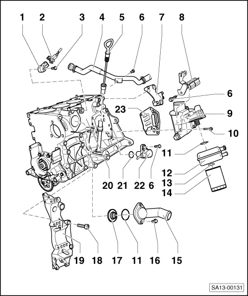
Golf Mk5
| Part II |

| 1 - | Knock sensor 1 -G61- |
| q | Gold-plated contacts |
| 2 - | Connector |
| q | Knock sensor 1 -G61- |
| q | Gold-plated contacts |
| q | Do not interchange → Current flow diagrams, Electrical fault finding and Fitting locations |
| 3 - | Bolt |
| q | 20 Nm |
| q | The torque setting influences the function of the knock sensor |
| 4 - | Coolant pipe |
| 5 - | Oil dipstick |
| q | The oil level must not be above the max. mark! |
| q | Markings → Fig. |
| 6 - | Bolt |
| q | 10 Nm |
| 7 - | Bracket |
| q | For ignition coil |
| 8 - | Bracket |
| 9 - | Oil filter bracket |
| q | Dismantling and assembling → Chapter |
| 10 - | Bolt |
| q | 15 Nm + 1/4 turn (90 °) further |
| q | Renew |
| 11 - | O-ring |
| q | Renew |
| 12 - | Oil cooler |
| q | Coat contact surface to oil filter bracket outside the seal with sealing paste -AMV 188 100 02- |
| q | Ensure clearance to adjacent components |
| 13 - | Nut |
| q | 25 Nm |
| 14 - | Oil filter |
| q | Loosen with strap wrench |
| q | Tighten by hand |
| q | Observe installation instructions on oil filter |
| 15 - | Connection |
| 16 - | Bolt |
| q | 15 Nm |
| 17 - | Thermostat |
| q | Checking: heat thermostat in water |
| q | Opening begins at approx. 86° C |
| q | Opening lift min. 7 mm |
| q | Removing and installing → Chapter |
| 18 - | Bolt |
| q | 45 Nm |
| 19 - | Compact bracket |
| q | For poly V-belt tensioner, alternator and air conditioner compressor |
| 20 - | Cylinder block |
| q | Removing and installing sealing flange and flywheel/drive plate |
| q | Removing and installing crankshaft → Chapter |
| q | Dismantling and assembling pistons and conrods |
| 21 - | O-ring |
| q | Renew if damaged |
| 22 - | Engine speed sender |
| 23 - | Gasket |
| q | Renew |
