volkswagen Workshop Repair Guides

Volkswagen Workshop Service and Repair Manuals

Securing engine on engine and gearbox supportVAS 6095 > < Removing and installing engine
Removing engine
Removing engine
The engine is removed downwards with gearbox.
–  Before removing, read the fault memories of all control units → Vehicle diagnostic tester; „Guided fault finding“.
  Note
t  All cable ties which are opened or cut through when engine is removed must be replaced in the same position when engine is installed.
t  Leave ignition key in ignition lock to prevent steering lock from engaging.
t  It is advisable to remove the front wheels before beginning engine removal. The vehicle can then be lowered on hoist until the brake disc splash plates are just above the floor. This provides the most ergonomic working position regarding accessibility of engine compartment components.
t  Some components cannot be removed, or removed only with difficulty, with the engine installed. Therefore, you should determine all defective components before removing engine and renew them while engine is removed.
t  To prevent damage to removed components, place them in the container for removed parts -V.A.G 1698-.
  Caution
When doing any repair work, especially in the engine compartment, pay attention to the following due to the cramped conditions:
t  Route all the various lines (e.g. for fuel, hydraulics, activated charcoal filter system, coolant and refrigerant, brake fluid and vacuum) and electrical wiring in their original positions.
t  To avoid damage to lines/wiring, ensure sufficient clearance to all moving or hot components.
–  Disconnect earth strap at battery with ignition switched off → Electrical system; Rep. gr.27.
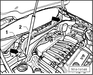
–  Completely remove air filter together with connecting hose to throttle valve module -J338- → Chapter.
–  Remove bracket from air filter.
–  Remove wiper arms, plenum chamber cover and plenum chamber bulkhead: → Electrical system; Rep. gr.92.
   
–  Unscrew securing bolts -arrows- of plenum chamber bulkhead -1- and remove together with resonance air pipe -2-.
Vehicles with anti-theft secured engine control unit
–  Remove the protective housing off the engine control unit → Chapter.
Continuation for all vehicles
–  Pull engine wiring harness connector off engine control unit.
  N10-10168
–  Release feed-through for engine wiring harness -arrow- and pull off upwards.
  A10-1574
–  Unscrew cable from alternator at fuse holder -arrow-.
  N10-10126
–  Unscrew earth cable from longitudinal member -arrow-.
  N10-10125
–  Open wiring guide catches on longitudinal member -arrows-.
–  Separate all connectors between engine wiring harness and body and lay engine wiring harness on engine.
  WARNING
Fuel supply line is pressurised. Wear eye protection and protective clothing to avoid possible injury and skin contact. Before loosening hose connections, wrap a cloth around the connection. Then release pressure by carefully pulling hose off connection.
–  Observe rules for cleanliness → Chapter.
  N10-0461
–  Detach fuel supply line -1- (black) and catch escaping fuel with a cloth.
–  Detach breather line -2- (white) and remove activated charcoal filter.
  Note
t  Press in securing ring to release fuel lines.
t  In vehicles with auxiliary heater, the fuel line -3- for the metering pump -V54- must also be detached.
–  Seal line so that fuel system is not contaminated by dirt.
  N10-10166
–  Separate Lambda probe connectors at plenum chamber bulkhead and free wiring.
1 - Lambda probe 2 -G108-, 6-pin connector (brown)
2 - Lambda probe -G39-, 6-pin connector (black)
–  Pull off/disconnect all electrical connections as necessary from engine/gearbox and lay to one side.
–  Pull vacuum line for brake servo off intake manifold.
–  Separate all further connection, vacuum and intake hoses from engine.
Vehicles with manual gearbox
–  Remove selector mechanism from gearbox → 6-speed manual gearbox 02Q four-wheel drive; Rep. gr.34.
–  Detach hydraulic line leading to hydraulic clutch slave cylinder → 6-speed gearbox 02Q four-wheel drive; Rep. gr.30.
Vehicles with DSG®
–  Remove selector mechanism from gearbox → 6-speed dual clutch gearbox 02E; Rep. gr.34.
Continuation for all vehicles
  WARNING
Steam may escape when expansion tank is opened. Wear eye protection and protective clothing to avoid eye injuries and scalding. Cover cap with cloth and open carefully.
–  Open and close expansion tank cap to release pressure in cooling system.
–  Remove noise insulation → General body repairs, exterior; Rep. gr.50
  N10-10167
–  Remove front parts of wheel housing liner → General body repairs, exterior; Rep. gr.66.
–  Bring lock carrier into service position → General body repairs, exterior; Rep. gr.50.
–  Pull connector off oil level and oil temperature sender -G266-.
–  Pull wiring retainer for oil level and oil temperature sender -G266- off subframe.
–  Remove front exhaust pipe with catalytic converters → Chapter.
  Note
The flexible joint in the front exhaust pipe must not be bent by more than 20° - risk of damage. To remove, ask for the assistance of a second mechanic.
–  Remove front propshaft → Final drive 02D, 0AV; Rep. gr.39
  Note
To prevent damage to condenser or to refrigerant lines/hoses, ensure that the lines and hoses are not stretched, kinked or bent.
To facilitate removing and installing engine without opening refrigerant circuit:
–  Remove poly V-belt → Chapter.
–  Open refrigerant line brackets on body.
–  Remove air conditioner compressor with connected refrigerant lines from ancillary bracket → Heating, air conditioning; Rep. gr.87.
  A10-1643
–  Attach air compressor -A- to lock carrier as shown (fastenings -1 and 2-).
–  Remove drive shaft protection for right drive shaft.
–  Remove drive shafts → Running gear, axles, steering; Rep. gr.40.
  N10-10216
–  Unscrew bolts -1…3- and remove pendulum support.
–  Drain coolant → Chapter.
–  Pull coolant hose quick-release couplings off radiator and heat exchanger.
–  Pull off coolant hoses leading to expansion tank.
Vehicles with auxiliary heater
–  Disconnect coolant hoses to auxiliary heater and to heater coolant shut-off valve -N279-.
Continuation for all vehicles
–  Insert engine bracket -T40074- in engine and gearbox jack -V.A.G 1383 A-.
  A10-1578
–  Remove adapter -T40074/1- from engine support -T40074- and screw with nut -1- onto cylinder block.
  N10-10292
–  Position engine support -T40074- on engine as shown and retighten adapter -T40074/1- with engine support -T40074--2-.
  N10-10178
–  Fit engine support -T40074- with M10x25 bolts on exhaust side as shown and tighten to approx. 20 Nm on cylinder block -arrows-.
–  Lift engine and gearbox lightly using engine and gearbox jack -V.A.G 1383 A-.
  N10-10146
–  Unbolt engine side of assembly mounting from engine bracket from above -arrows-.
  N10-0437
–  Unbolt gearbox side of assembly mounting from gearbox bracket -arrows- from above.
  Note
t  To remove securing bolts use a stepladder -VAS 5085-.
t  Engine with gearbox must be guided carefully when lowering to prevent damage to bodywork.
–  Carefully lower engine with gearbox.
  N10-10147

Securing engine on engine and gearbox supportVAS 6095 > < Removing and installing engine