
Golf Mk5
 Note
Note
|
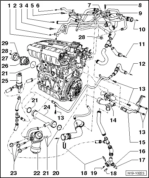
| 1 - | From auxiliary heater |
| q | Only vehicles with extra equipment |
| 2 - | To auxiliary heater |
| q | Only vehicles with extra equipment |
| 3 - | 45 Nm |
| 4 - | From bottom of expansion tank |
| 5 - | 10 Nm |
| 6 - | To top of expansion tank |
| 7 - | From heater coolant shut-off valve -N279- |
| q | Only vehicles with extra equipment |
| 8 - | 10 Nm |
| 9 - | To heater coolant shut-off valve -N279- |
| q | Only vehicles with extra equipment |
| 10 - | To heat exchanger |
| 11 - | From gearbox oil cooler |
| 12 - | To gearbox oil cooler |
| 13 - | 8 Nm |
| 14 - | Thermostat housing |
| q | Assembly overview - thermostat housing → Chapter |
| q | Removing and installing → Chapter. |
| 15 - | Retainer |
| 16 - | O-ring |
| q | Renew. |
| 17 - | Radiator outlet coolant temperature sender -G83- |
| 18 - | Retaining clip |
| q | Check for secure seating. |
| 19 - | From bottom of radiator. |
| 20 - | To top of radiator |
| 21 - | O-ring |
| q | Renew. |
| 22 - | Oil filter bracket |
| q | With oil cooler. |
| 23 - | 23 Nm |
| 24 - | Coolant pipe |
| q | To thermostat housing. |
| 25 - | Continued coolant circulation pump -V51- |
| q | Bolted to ancillary unit bracket to 8 Nm. |
| q | To remove, remove bracket for ancillaries → Heating, air conditioning; Rep. gr.87. |
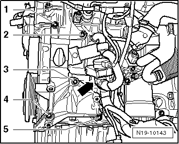
| q | Location of continued coolant circulation pump -V51- → Fig. |
| q | Checking continued coolant circulation pump -V51- → Chapter |
| 26 - | Coolant pump |
| q | Check for ease of movement. |
| q | Removing and installing → Chapter. |
| 27 - | Belt pulley |
| q | For coolant pump. |
| q | Removing and installing → Chapter, Removing and installing coolant pump |
| 28 - | 20 Nm |
| 29 - | 8 Nm |
|
|