volkswagen Workshop Repair Guides

Volkswagen Workshop Service and Repair Manuals

Removing and installing camshaft adjuster > < Assembly overview - cover
Checking valve timing
Special tools and workshop equipment required
   
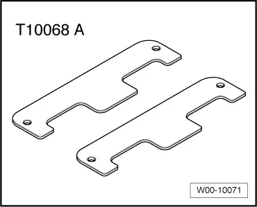
t  Camshaft bar -T10068 A-
Test procedure
–  Remove cylinder head cover and intake manifold → Chapter.
  W00-10071
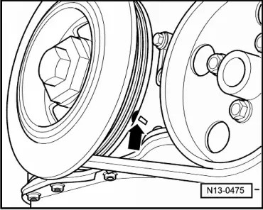
–  Set crankshaft to TDC No. 1 cylinder marking -arrow- by turning crankshaft on the vibration damper securing bolt in direction of engine rotation.
  N13-0475
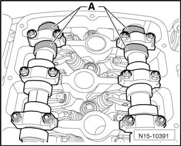
–  Cams -A- of cylinder 1 must face each other.
  N15-10391
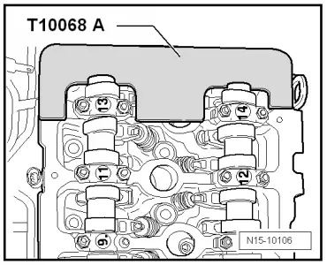
–  Insert camshaft bar -T10068 A- in both shaft grooves.
  Note
  N15-10106
The grooves of the camshafts might not be exactly vertical due to the function of camshaft adjusters. Therefore, if necessary, move the camshafts back and forth slightly when inserting the camshaft bar -T10068 A- using an open-end spanner.
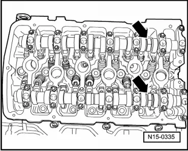
Check setting marks of camshaft adjusters against marks on control housing:
  N15-0335
l  „Arrow“-1- on the camshaft adjuster of the inlet camshaft must align with the left notch -2- on the control housing. Markings on valve timing housing → Fig.
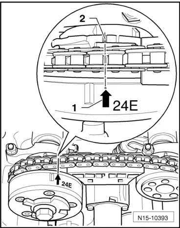
  N15-10393
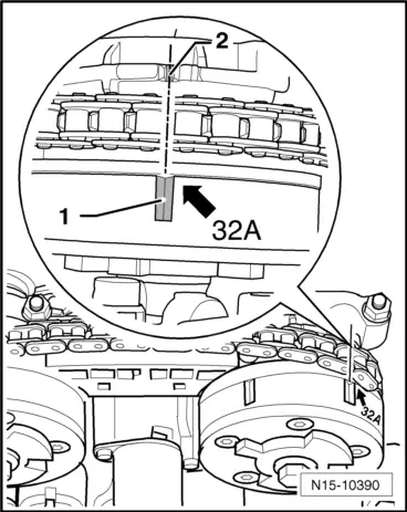
l  Marking -1- on camshaft adjuster of exhaust camshaft, to which the „arrow“ points, must align with left notch -2- on valve timing housing. Markings on valve timing housing → Fig.
  Note
A slight offset between marking -1- and notch -2- is permissible.
  N15-10390
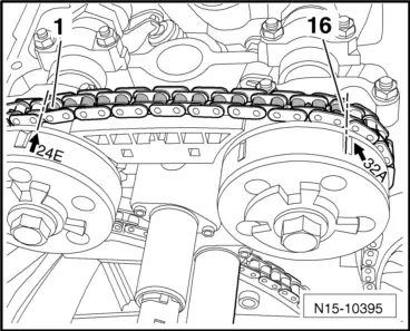
–  The gap between markings of camshaft adjuster must be exactly 16 rollers of camshaft timing chain.
  Note
Figure shows view with cover removed.
If the markings do not align:
–  Adjust valve timing → Chapter.
If the markings align:
–  Install cylinder head cover and intake manifold → Chapter.
  N15-10395
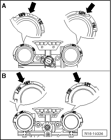
Markings on valve timing housing on MPI engines
-A- View from flywheel end
-B- View from vibration damper end
The markings on camshaft adjusters must align with notches -arrows-.
  N15-10336

Removing and installing camshaft adjuster > < Assembly overview - cover