
Golf Mk5
| Removing and installing camshaft timing chain and intermediate shaft drive chain |
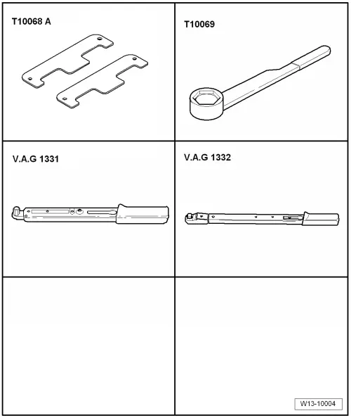
| Special tools and workshop equipment required |
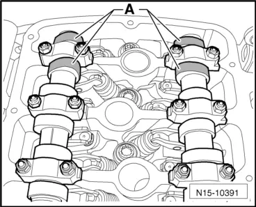
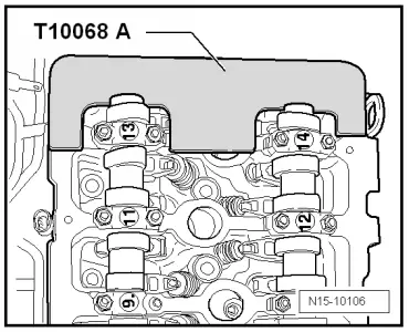
| t | Camshaft bar -T10068 A- |
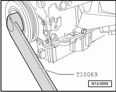
| t | Counterhold tool -T10069- |
| t | Torque wrench -V.A.G 1331- |
| t | Torque wrench -V.A.G 1332- |
| t | Sealant -D 176 501 A1- |
|
|
|
|
|
|
|
|
|
|
|
|
|
|
|
|
|
|
|
|
|
 Note
Note
|
|
|
|
|
|
|
|
Note
|
|
|
|
|
|
|
|
Note
|
|
|
|
|
|
|
|
|
|
Note |
|
|
|
|
|
|
|
|
|
|
|
Note
|
|
Note
|
|
Note
|
|
|
|
|
|
|
|
|
|
| Component | Nm | |
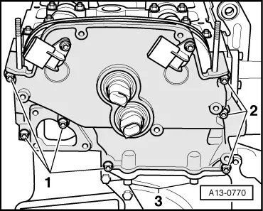
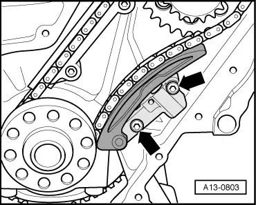
| Bolts for guide rail to cylinder block | 10 | |
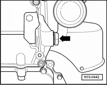
| Chain tensioner to cylinder block | 8 | |
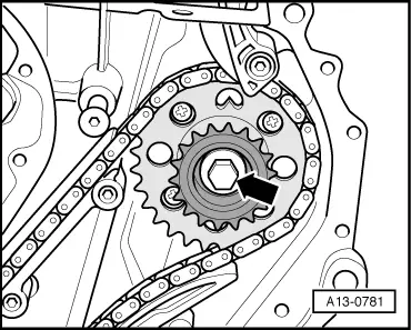
| Sprockets to intermediate shaft | 60 + 90° | |
| Camshaft adjuster to camshafts | 60 + 90° | |
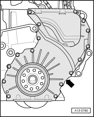
| Bottom cover for timing chains to cylinder block | 10 | |
| Top cover for camshaft timing chain | M6 | 10 |
| M8 | 23 | |
| Chain tensioner for camshaft timing chain to cylinder head | 40 | |