
Golf Mk5
| Assembly overview |

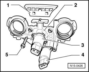
| 1 - | 5 Nm + 1/8 turn (45°) further |
| 2 - | Exhaust camshaft bearing cap |
| q | Installation sequence → Chapter. |
| 3 - | Seal |
| q | Renew if leaking. |
| q | When installing valve timing housing, lightly lubricate contact surfaces of seal. |
| q | When replacing seals, do not spread too widely. |
| 4 - | Exhaust camshaft |
| q | Checking radial clearance with Plastigage; wear limit: 0.1 mm. |
| q | Runout: max. 0.04 mm. |
| q | Checking axial clearance → Fig.. |
| q | Identification and valve timing → Fig. |
| q | Removing and installing → Chapter. |
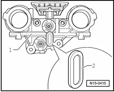
| 5 - | Valve timing housing |
| q | Lightly lubricate contact surfaces of oil seals before installing. |
| q | Dismantling and assembling → Fig.. |
| q | Before installing valve timing housing, check strainer for soiling → Fig.. |
| q | Removing and installing → Chapter. |
| 6 - | Camshaft timing chain |
| q | Before removing, mark direction of rotation (installation position) → Fig.. |
| q | Installing → Chapter. |
| 7 - | Exhaust camshaft adjuster |
| q | Identification: 32A. |
| q | Only rotate engine when camshaft adjuster is installed and chain is fitted |
| q | Installing → Chapter. |
| 8 - | 60 Nm + 1/4 turn (90°) further |
| q | Renew. |
| q | Contact surface of sender wheel must be dry around bolt head when installed. |
| q | To remove and install, counterhold with 32 mm open-end spanner on camshaft → Chapter |
| 9 - | Inlet camshaft adjuster |
| q | Identification: 24E |
| q | Only rotate engine when camshaft adjuster is installed and chain is fitted |
| q | Installing → Chapter. |
| 10 - | Cylinder head height |
| q | Minimum height: a = 139.9 mm. |
| 11 - | Valves |
| q | Do not rework, only lapping-in is permitted. |
| q | Valve dimensions → Fig.. |
| 12 - | Cylinder head |
| q | Check for distortion → Fig.. |
| q | Removing and installing → Chapter. |
| q | Reworking valve seats → Chapter. |
| q | After renewing, renew entire coolant. |
| 13 - | Support element |
| q | Before installing, check camshaft axial clearance → Fig.. |
| q | Do not interchange. |
| q | With hydraulic valve clearance compensation. |
| 14 - | Valve stem seal |
| q | Renewing → Chapter. |
| 15 - | Securing clip |
| q | Check for secure seating. |
| 16 - | Roller rocker finger |
| q | Before installing, check camshaft axial clearance → Fig.. |
| q | Do not interchange. |
| q | Check roller bearing for ease of movement. |
| q | Oil contact surface. |
| q | When installing, secure to supporting element using securing clip. |
| 17 - | Valve spring |
| q | Note installation position. |
| q | Removing and installing → Chapter. |
| 18 - | Valve spring plate |
| 19 - | Valve cotters |
| 20 - | Inlet camshaft bearing cap |
| q | Installation sequence → Chapter. |
| 21 - | Inlet camshaft |
| q | Checking radial clearance with Plastigage; wear limit: 0.1 mm. |
| q | Runout: max. 0.04 mm. |
| q | Checking axial clearance → Fig.. |
| q | Identification and valve timing → Fig. |
| q | Removing and installing → Chapter. |
|
|