
Golf Mk5
| Part II: Assembly overview - crankshaft drive |
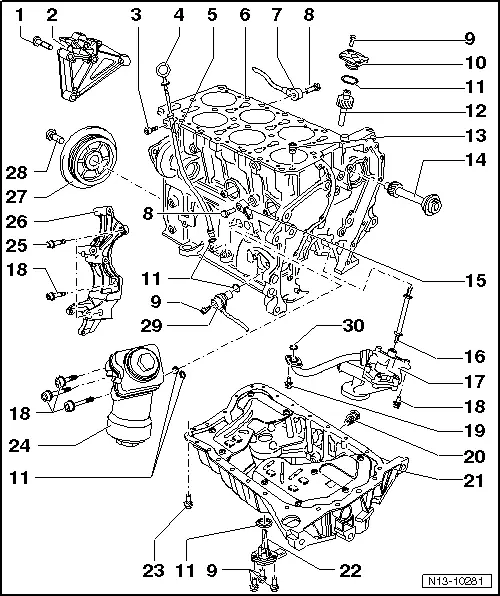
| 1 - | 45 Nm |
| 2 - | Engine bracket |
| 3 - | 5 Nm |
| q | Secured to intake manifold. |
| 4 - | Oil dipstick |
| q | The oil level must not be above the max. mark! |
| q | Markings → Fig.. |
| 5 - | Guide tube |
| q | For oil dipstick. |
| q | Secured with bolt to intake manifold. |
| 6 - | Cylinder block |
| q | Removing and installing sealing flange and dual-mass flywheel → Chapter. |
| q | Removing and installing crankshaft → Chapter. |
| q | Dismantling and assembling pistons and conrods → Chapter |
| 7 - | Knock sensor 1 -G61- |
| q | Fitting location: between cylinder 1 and cylinder 3. |
| 8 - | 20 Nm |
| q | The specified torque influences the function of the knock sensor. |
| 9 - | 10 Nm |
| 10 - | Oil pump drive cover |
| 11 - | O-ring |
| q | Renew. |
| q | Lubricate before installing. |
| 12 - | Oil pump drive |
| 13 - | Oil non-return valve, 5 Nm |
| q | Note installation position. |
| q | Clean if badly soiled |
| q | See note → Chapter. |
| 14 - | Intermediate shaft |
| 15 - | Knock sensor 2 -G66- |
| q | Fitting location: between cylinder 4 and cylinder 6. |
| 16 - | Drive shaft |
| q | For oil pump drive. |
| 17 - | Oil pump |
| q | Assembly overview - oil pump → Chapter |
| 18 - | 23 Nm |
| 19 - | 8 Nm |
| q | Renew. |
| 20 - | Oil drain plug, 30 Nm |
| q | Renew seal |
| 21 - | Sump |
| q | Removing and installing → Chapter |
| 22 - | Oil level and oil temperature sender -G266- |
| 23 - | 12 Nm |
| 24 - | Oil filter bracket |
| q | Assembly overview - oil filter bracket → Chapter |
| q | Coolant hose schematic diagram → Chapter. |
| 25 - | Fitted bolt, 23 Nm |
| 26 - | Bracket for ancillaries |
| q | For alternator, air conditioner compressor and power-assisted steering vane pump |
| 27 - | Vibration damper |
| q | Removing and installing → Chapter |
| 28 - | 100 Nm + 1/2 turn (180°) further. |
| q | Removing and installing → Chapter |
| 29 - | Engine speed sender -G28- |
| 30 - | Seal |
| q | Renew if damaged. |