
Golf Mk5
| Assembly overview: subframe, anti-roll bar, suspension links |
 Caution
|
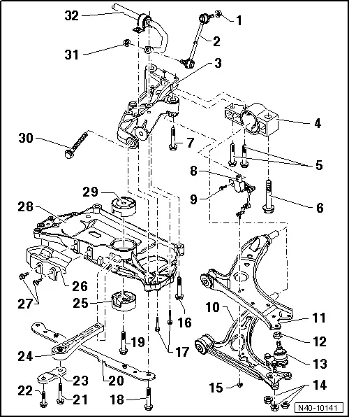
| 1 - | Nut |
| q | 65 Nm |
| q | When tightening, counterhold on hexagon socket of joint stub. |
| q | Self-locking |
| q | Always renew after removing. |
| 2 - | Coupling rod |
| q | Link between anti-roll bar and suspension strut |
| 3 - | Bracket |
| q | Fixing position → Fig. |
| q | If bracket is renewed, the wheels must be aligned → Chapter |
| 4 - | Mounting bracket |
| q | Fixing position → Fig. |
| q | With bonded rubber bush |
| 5 - | Bolt |
| q | 50 Nm + 90° further |
| q | Always renew after removing. |
| 6 - | Bolt |
| q | M12 x 1.5 x 90 |
| q | 70 Nm + 90° further |
| q | Always renew after removing. |
| 7 - | Bolt |
| q | M12 x 1.5 x 90 |
| q | 70 Nm + 90° further |
| q | Always renew after removing. |
| 8 - | Front left vehicle level sender -G78- |
| q | Removing and installing → Chapter. |
| q | Can be tested in guided fault finding using → Vehicle diagnostic tester |
| 9 - | Bolt |
| q | 9 Nm |
| 10 - | Suspension link |
| q | Different versions of suspension links are possible (cast steel, aluminium). |
| q | Allocation → Electronic parts catalogue „ETKA“ |
 Note
Note| A mixed installation of suspension links of different types or made of different materials is not permissible. |
| q | If damaged, also renew swivel joint. |
| q | Removing and installing → Chapter. |
| q | Renew mounting → Chapter |
| 11 - | Suspension link |
| q | Different versions of suspension links are possible (welded steel sheet, single-shell steel sheet). |
| q | Allocation → Electronic parts catalogue „ETKA“ |
Note| A mixed installation of suspension links of different types or made of different materials is not permissible. |
| q | If damaged, also renew swivel joint. |
| q | Removing and installing → Chapter. |
| q | Renew mounting → Chapter |
| 12 - | Nut |
| q | M12 x 1.5 |
| q | 60 Nm |
| q | Self-locking |
| q | Always renew after removing. |
| 13 - | Swivel joint |
| q | Checking → Chapter |
| q | Removing and installing → Chapter. |
| q | Renew together with suspension link if suspension link is damaged |
| 14 - | Nut |
| q | For cast steel suspension link: 60 Nm |
| q | For sheet steel and forged aluminium suspension link: 100 Nm |
| q | Self-locking |
| q | Always renew after removing. |
| 15 - | Nut |
| q | 9 Nm |
| 16 - | Bolt |
| q | M12 x 1.5 x 100 |
| q | 70 Nm + 90° further |
| q | Always renew after removing. |
| 17 - | Bolt |
| q | 20 Nm + 90° further |
| q | Always renew after removing. |
| 18 - | Bolt |
| q | M12 x 1.5 x 75 |
| q | 70 Nm + 90° further |
| q | Always renew after removing. |
| 19 - | Bolt |
| q | M14 x 1.5 x 70 |
| q | 100 Nm + 90° further |
| q | Do not tighten until pendulum support is bolted to gearbox |
| q | Always renew after removing. |
| 20 - | Bracket for skid plate |
| q | Allocation → Electronic parts catalogue „ETKA“ |
| 21 - | Bolt |
| Always observe size and strength class of the bolt. Different torque specifications apply. |
| q | M10 x 75 strength class 8.8: 40 Nm and turn 90° further |
| q | M10 x 75 strength class 10.9: 50 Nm and turn 90° further |
Caution
|
| q | Always renew after removing. |
| 22 - | Bolt |
| Always observe strength class of the bolt. Different torque specifications apply. |
| q | M10 x 35 strength class 8.8: 40 Nm and turn 90° further |
| q | M10 x 35 strength class 10.9: 50 Nm and turn 90° further |
Caution
|
| q | Always renew after removing. |
| 23 - | Bracket to pendulum support |
| q | Not an individual part |
| 24 - | Pendulum support |
| q | Bolt first to gearbox and then to subframe |
| q | Various versions |
| q | Allocation → Electronic parts catalogue „ETKA“ |
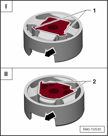
| 25 - | Lower bonded rubber bush for pendulum support |
| q | Pressing out and in for vehicles with front-wheel drive → Chapter |
| q | Pressing out and in for vehicles with four-wheel drive → Chapter |
| q | Different versions → Fig. |
| q | Allocation → Electronic parts catalogue „ETKA“ |
| 26 - | Shield |
| q | For vehicles with front-wheel drive only |
| 27 - | Bolt |
| q | 6 Nm |
| q | Self-locking |
| 28 - | Subframe |
| q | Various versions |
| q | Removing and installing without steering box → Chapter |
| q | Removing and installing with steering box → Chapter |
| q | Allocation → Electronic parts catalogue „ETKA“ |
| 29 - | Upper bonder rubber bush for pendulum support |
| q | Pressing out and in for vehicles with front-wheel drive → Chapter |
| q | Pressing out and in for vehicles with four-wheel drive → Chapter |
| q | Different versions → Fig. |
| q | Allocation → Electronic parts catalogue „ETKA“ |
| 30 - | Bolt |
| q | M12 x 1.5 x 110 |
| q | 70 Nm + 180° further |
| q | Always renew after removing. |
| q | Always tighten threaded connections in unladen position: |
| Golf → Chapter |
| Golf Plus, CrossGolf → Chapter |
| 31 - | Nut |
| q | 65 Nm |
| q | When tightening, counterhold on hexagon socket of joint stub. |
| q | Self-locking |
| q | Always renew after removing. |
| 32 - | Anti-roll bar |
| q | Various versions |
| q | Allocation → Electronic parts catalogue „ETKA“ |
| q | Removing and installing → Chapter. |
Note
|
|